Executive Summary Stainless steel coils—particularly slit coils with premium 2B, BA, No. 4, and No. 8 mirror finishes—are highly susceptible to surface scratching, edge crimping, and iron contamination during transit. An automated packaging and handling system transfers slit coils in an eye-to-sky (vertical axis) orientation across polyurethane-coated conveyors, applies through-the-eye helical protective wrapping, and completes mechanical downending and pallet stacking without direct manual rigging. This engineering guide details the mechanical station flow, kinematic film calculation formulas, surface protection protocols, and equipment selection matrices for metal service centers.
The Challenge of Handling Stainless Steel Coils
Unlike structural carbon steel, cold-rolled stainless steel strip is specified for stringent aesthetic and sanitary applications. The surface oxide film (chromium-rich passive layer) and mirror-like finishes must remain completely free of friction marks, tool indentations, and particulate imbedding.
Manual packaging using overhead cranes, C-hooks, or nylon slings introduces severe quality risks:
- Point-load surface rubbing: Hoist acceleration causes microscopic shifting between coil wraps, leading to friction rub marks (fretting corrosion).
- Carbon contamination: Direct contact with unlined steel transfer tables or bare steel forks introduces free iron particles, causing severe rust blooms during overseas ocean transit.
- Telescoping and edge damage: High-tension manual poly strapping concentrates lateral load on the outer wraps, deforming delicate slit edges (strip gauge 0.3–1.5 mm).
The automated packing solution maintains continuous, soft-contact mechanical support throughout conveyance, orbital eye-through wrapping, and robotic or mechanical pallet stacking.
Stainless Steel Surface Finish Grades and Sensitivity
Selecting line operating parameters requires calibrating clamping pressures and film tension to the incoming strip finish:
| Finish Grade | Mechanical Characteristics | Damage Vulnerability | Handling and Clamping Threshold |
|---|---|---|---|
| 2B | Smooth, cold-rolled, skin-passed; standard industrial mill finish | Medium; visible scratching compromises weld line aesthetics | Polyurethane roller contact; line pressure ≤ 0.4 MPa |
| BA (Bright Annealed) | Mirror-reflective; processed in reducing atmosphere | High; minute scuffs or thumbprints cause lot rejection | Non-marking Shore A 85 PU sleeves; zero bare-hand contact |
| No. 4 (Brushed/Satin) | Unidirectional abrasive grain (150–240 grit) | Medium-High; cross-directional scratches ruin linear grain | Edge protection required; longitudinal centering only |
| No. 8 (True Mirror) | Mechanically buffed with ultra-fine compounds; defect-free | Extreme; zero allowable mechanical contact on outer face | Double-layer film wrapping; air-cushioned or vacuum staging |
| Hairline (HL) | Continuous long-grain linear pattern | High; sensitive to localized slip friction during acceleration | Progressive S-curve conveyor acceleration ≤ 0.2 m/s² |
Downgrading a BA coil to a 2B commercial value due to transit scuffing can result in a 10% to 25% financial loss per metric ton.
How the Automated Packing Line Operates
The automated slit coil packing system integrates four discrete stations into a continuous, PLC-controlled cell, operating in an eye-to-sky (vertical axis) orientation to maximize coil stability.
[Slitter Exit / Turnstile]
           │
           ▼
[Polyurethane Roller Conveyor] ── (Eye-to-Sky Centering)
           │
           ▼
[Through-the-Eye Ring Wrapper] ── (Helical Stretch / VCI Application)
           │
           ▼
[Automatic Labeling Station]   ── (Outer Diameter / Face Thermal Barcode)
           │
           ▼
[Hydraulic Stacker / Downender] ── (Pallet Loading / Turnstile Accumulation)
Step 1 — Infeed and Eye-to-Sky Conveyance
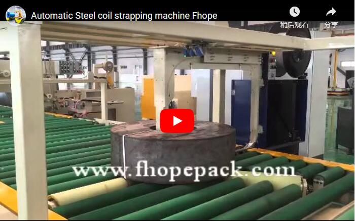
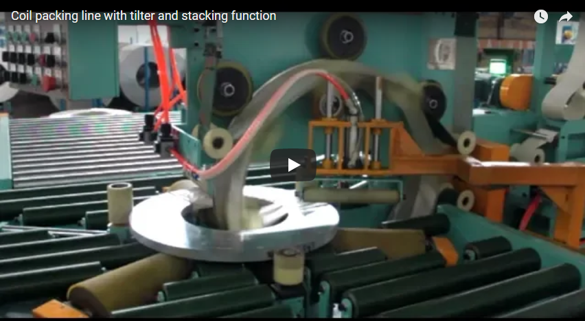
Slit coils exit the slitter recoil mandrel onto a turnstile and downender, landing flat (eye-to-sky) on powered roller conveyors.
- All rollers are vulcanized with high-grade polyurethane (Shore A 85–90, minimum 12 mm wall thickness) to prevent contact with bare ferrous metal.
- Optical sensor arrays detect the coil’s outer diameter (OD) and inner diameter (ID), triggering pneumatic centering arms that position the coil concentric to the wrapping center line without edge scuffing.
Step 2 — Through-the-Eye Orbital Film Wrapping
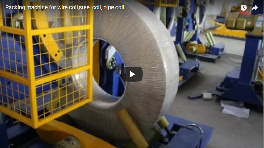
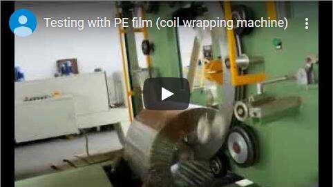
The coil conveys into the wrapping station, where a split shuttle ring penetrates the vertical center bore.
- The ring rotates a film dispenser through the coil eye while conical PU-covered support rollers rotate the coil around its vertical centerline.
- This dual-axis rotation lays down a continuous, tightly overlapped helical shroud across the ID, OD, and both horizontal faces.
- Digital magnetic particle tensioners maintain consistent web tension (15–40 N) regardless of roll diameter depletion, preventing edge crimp on ultra-thin slit widths.
| Station Parameter | Engineering Specification |
|---|---|
| Wrapping Mechanism | C-frame orbital shuttle ring (through-the-eye) |
| Film Compatibility | LLDPE stretch film, VCI anti-corrosion film, woven PP tape |
| Film Web Width | 100 mm to 300 mm |
| Film Thickness Range | 20 µm to 50 µm |
| Ring Rotation Speed | Variable frequency drive (VFD), 40 to 120 RPM |
| Coil Rotation Speed | 1.5 to 4.5 RPM (synchronized to target overlap) |
Step 3 — Automated Tagging and Weight Inspection
The wrapped coil indexes to the inline inspection station:
- Integrated load cells within the roller conveyor capture net weight to ±0.2 kg accuracy.
- A robotic or pneumatic applicator applies a thermal barcode label directly to the outer wrap or coil side wall, synchronizing data with the facility MES/ERP via industrial Ethernet.
Step 4 — Mechanical Pallet Stacking
A hydraulic scissor-lift stacker fitted with an expanding ID mandrel or perimeter grab arms lifts the wrapped coil from the conveyor:
- The coil is transferred to a dual-station pallet turntable.
- Programmable stacking patterns nest coils 1 to 6 layers high onto wooden, composite, or steel skids.
- Non-metallic or pressboard separators can be placed automatically between coils to prevent interlayer vacuum locking and outer face chafing.
Film Consumption and Overlap Engineering Calculations
Specifying film roll capacity, cycle times, and packaging consumables requires exact geometric equations that factor in coil geometry, mechanical overlap, and dispenser pre-stretch ratios.
       ┌──────────────────────── OD ────────────────────────┐
       │                                                    │
       ▼                                                    ▼
       ┌──────────────────┬──────────────┬──────────────────┐ ──┐
       │                  │              │                  │   │
       │    Coil Wall     │  Center Eye  │    Coil Wall     │   │ Width
       │      (t_w)       │     (ID)     │      (t_w)       │   │  (W)
       │                  │              │                  │   │
       └──────────────────┴──────────────┴──────────────────┘ ──┘
1. Geometric Section Perimeter
The length of film required to make a single wrap around the radial cross-section of the coil:
P_sec = 2 × (t_w + W) = 2 × [((OD - ID) / 2) + W]
Where:
OD= Coil outer diameter (mm)ID= Coil inner diameter (mm)W= Coil slit width (mm)t_w= Radial wall thickness (mm) =(OD - ID) / 2
2. Overlap Ratio and Mean Core Circumference
To achieve uniform hermetic sealing, consecutive film wraps must overlap along the maximum outer perimeter:
Advance per wrap (A_w) = F_w × (1 - O_r)
Where:
F_w= Film width applied on the coil (mm)O_r= Required overlap ratio (e.g., 0.30 for 30%, 0.50 for 50%)
The total number of wraps (N_wraps) required to complete a full 360° rotation around the coil:
N_wraps = (π × OD) / A_w = (π × OD) / [F_w × (1 - O_r)]
3. Total Film Consumption (Accounting for Pre-Stretch)
If the machine utilizes a power pre-stretch carriage, the un-stretched film pulled from the core roll is significantly less than the film applied to the product:
L_applied = N_wraps × P_sec
L_core = L_applied / (1 + S_r)
Where:
L_applied= Net length of stretched film on the coil (m)S_r= Carriage pre-stretch ratio (e.g., 2.0 for 200% power pre-stretch)L_core= Actual linear meters consumed from the raw film roll (m)
Engineering Worked Example
Consider a precision-slit BA stainless steel coil under export shipping specifications:
| Parameter | Metric Value |
|---|---|
Outer Diameter (OD) |
1200 mm (1.20 m) |
Inner Diameter (ID) |
508 mm (0.508 m) |
Strip Width (W) |
300 mm (0.30 m) |
Film Width (F_w) |
200 mm (0.20 m) |
Target Overlap Ratio (O_r) |
40% (0.40) |
Pre-Stretch Ratio (S_r) |
150% (1.50) |
- Radial Wall Thickness:
t_w = (1200 - 508) / 2 = 346 mm - Section Perimeter:
P_sec = 2 × (346 + 300) = 1292 mm = 1.292 m - Linear Advance per Wrap:
A_w = 200 × (1 - 0.40) = 120 mm = 0.12 m - Total Number of Wraps:
N_wraps = (π × 1.20) / 0.12 ≈ 3.770 / 0.12 ≈ 31.4(Round up to 32 wraps) - Applied Film Length:
L_applied = 32 × 1.292 m = 41.34 m - Core Film Consumed:
L_core = 41.34 / (1 + 1.50) = 41.34 / 2.50 = 16.54 m per coil
Film Selection Matrix for Stainless Steel Packaging
The film chemistry and mechanical grade directly influence corrosion resistance and transit security:
| Packaging Material | Tensile Strength (MD/TD) | Puncture Resistance | Optical Clarity | Primary Packaging Objective |
|---|---|---|---|---|
| Cast LLDPE (Multi-layer) | 35 MPa / 28 MPa | Medium-High | Superior (> 92%) | High-speed orbital wrapping; visual surface QC verification |
| Blown LLDPE | 45 MPa / 40 MPa | Superior | Hazy / Translucent | Rough-edge slit coils; high-tensile resistance against burrs |
| VCI Impregnated Film | 30 MPa / 25 MPa | High | Low-Medium (Green/Blue) | Sea freight shipments; active anti-corrosion barrier |
| Woven Polypropylene (PP) | 80 MPa / 75 MPa | Extreme | Opaque | Heavy gauge coils; exterior armor against handling impacts |
Line Integration and Layout Specification Checklist
To receive an exact technical layout, cycle-time simulation, and mechanical proposal within 48 hours, compile the following shop-floor constraints:
- Coil Dimensional Envelope: Minimum and maximum OD, ID, and Width (mm).
- Weight Capacity Requirements: Minimum and maximum coil weight (kg).
- Surface Finish Mix: Ratio of 2B, BA, No. 4, or No. 8 coils processed per shift.
- Pre-Wrap Edge Condition: Presence of slitter burrs (determines film puncture rating).
- Throughput Target: Target coils per hour (CPH) or cycle time per individual coil (seconds).
- Packaging Material Recipe: Single stretch layer, composite stretch + paper, or VCI wrap.
- Downstream Stacking Constraints: Maximum pallet weight, stack height limit, and timber skid dimensions.
- Available Floor Space and Flow: In-line straight pass-through, L-shape, or 180° return layout.
- Field Bus Communication: Siemens Profinet, Rockwell EtherNet/IP, or discrete I/O integration.
Safety Standards and Risk Assessment Protocols
Because automated coil lines process high-density, multi-ton rotating steel units, machinery design must adhere to regional and international safety mandates:
- Mechanical Guarding (ISO 12100 & EN 415-10): Perimeter safety fencing with 2200 mm height and interlocked safety access doors fitted with solenoid-locking RFID switches.
- Optical Enclosure: Type 4 safety light curtains mounted across conveyor ingress and pallet discharge bays, integrated with muting arms to distinguish coils from maintenance personnel.
- Fail-Safe Clamping and Lifting: Hydraulic stackers integrate counterbalance check valves directly into the cylinder manifolds, preventing mechanical carriage drop in the event of catastrophic pressure loss.
- LOTO Provisions: Single-point pneumatic exhaust valves and electrical isolators compliant with OSHA 1910.147 requirements.
Engineering FAQ
Q: Why process narrow stainless slit coils in an eye-to-sky orientation instead of eye-horizontal?
A: Narrow slit coils (widths 1000 mm) exhibit a high aspect ratio. In an eye-horizontal orientation (axis parallel to floor), they have minimal lateral balance and easily tip or telescope. Eye-to-sky conveyance (axis vertical) places the flat width face onto polyurethane rolls, ensuring total structural stability and allowing continuous through-the-eye wrapping.
Q: How does the system prevent strip burrs from puncturing the stretch film?
A: Slit coils with excessive burrs are wrapped using blown multi-layer LLDPE film rather than cast film. Furthermore, the PLC automatically reduces film tension across the first two foundational wraps while increasing overlap to 50%, forming a puncture-resistant perimeter cushion before high-tension wrapping commences.
Q: Can this line package coils with paper interleaving?
A: Yes. The shuttle ring dispenser can be fitted with dual reels, feeding heavy Kraft paper or VCI paper in tandem with an outer stretch film envelope, ensuring total moisture barrier and mechanical abrasion resistance.
Next Steps for Project Implementation
To engineer an automated stainless steel coil wrapping and stacking line customized to your slitting facility:
- Submit Line Specifications: Email your coil dimensional envelope (ID/OD/Width), weights, and finish types to info@fhopepack.com.
- Technical Proposal (Within 48 Hours): Our packaging systems group delivers a complete General Arrangement (GA) drawing, cycle-time analysis, and consumable cost calculation.
- Engineering Layout Verification: Connect with our senior project engineers to coordinate floor footprint, roller elevations, and PLC handshakes with your upstream slitter.
Technical References
- General Packaging Machine Directives: ISO 12100:2010 Safety of Machinery
- Safety of Packaging Machines: EN 415-10:2014 General Safety Requirements
- Automated Coil System Layouts: FHOPE Heavy Coil Handling Solutions
Last Technical Review: October 2026 | FHOPE Industrial Automation & Packaging Division