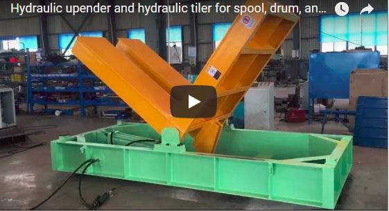
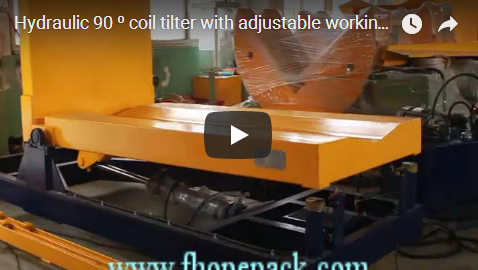
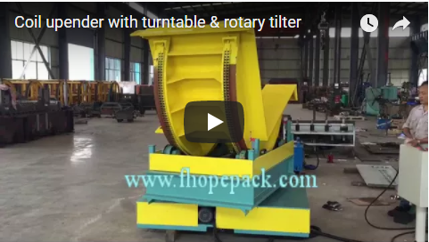
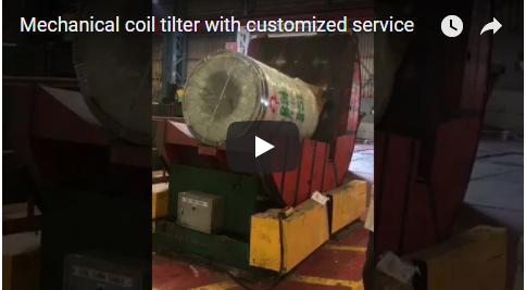
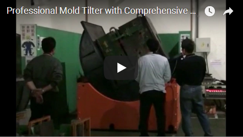
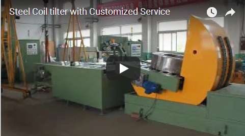
Executive Summary: A 180° upender is a precision material handling system engineered to invert heavy industrial loads—such as steel coils, stone blocks, or copper ingots—between horizontal and vertical orientations. Designed for automated packaging workflows, these machines replace hazardous manual tilting with controlled mechanical rotation. Standard models operate within a 20 to 40-second single flip cycle, support carrying capacities between 500 kg and 5000 kg, and achieve processing rates of 100 to 150 units per hour. Operating at ≤ 75 dB, they integrate seamlessly into strapping and wrapping lines while eliminating ergonomic injury risks and production bottlenecks.
[VIDEO PLACEHOLDER]
🛠️ Core Questions
What is a 180° upender and how does it work?
A 180° upender is a precision material handling system that inverts heavy industrial loads—such as steel coils, stone blocks, or copper ingots—between horizontal and vertical orientations. Engineered for automated packaging workflows, it replaces hazardous manual tilting with controlled mechanical rotation.
These machines function through a synchronized drive system that engages a cradle or platform to secure the load during inversion. The rotation mechanism is typically powered by either electro-hydraulic cylinders or electromechanical screw jacks, depending on tonnage requirements. A standard single flip cycle completes in 20 to 40 seconds, allowing facilities to process 100 to 150 units per hour without disrupting downstream packaging equipment. By automating the inversion process, manufacturers eliminate manual labor bottlenecks, reduce workplace injury claims, and ensure consistent load alignment for strapping or wrapping stations. The operating noise remains at or below 75 dB, which aligns with typical facility acoustic compliance thresholds and minimizes worker fatigue during extended shifts.
What are the typical load capacity and cycle time ranges?
Standard industrial upenders handle carrying capacities between 500 kg and 5000 kg, completing a single flip cycle in 20 to 40 seconds. This operational rhythm supports a processing throughput of 100 to 150 units per hour, directly aligning with downstream strapping and wrapping equipment speeds.
Load capacity is determined by the structural frame rating, slewing ring bearing specifications, and drive motor torque. Facilities handling lighter materials often operate within the 500 kg to 2000 kg range, while heavy manufacturing sectors frequently utilize units rated up to 5000 kg. Cycle time remains relatively consistent across this spectrum, though eccentric or unbalanced loads may require slightly extended inversion durations to maintain stability. The 100 to 150 units per hour throughput metric is calibrated to match standard stretch wrapper and strapping machine speeds, preventing upstream congestion. When selecting capacity, engineers must account for dynamic moment loads, as off-center weight distribution increases stress on the rotation axis. Verifying maximum moment ratings with the supplier ensures the frame deflection remains within acceptable engineering tolerances during peak operation.
What are the main applications of a coil upender in packaging lines?
These machines primarily reorient cylindrical coils from eye-to-sky to eye-to-wall configurations, enabling automated stretch wrapping and strapping. They also serve stone and copper processing facilities as turnover machines, eliminating manual labor bottlenecks and ensuring consistent load alignment for downstream automation.
In packaging environments, the upender is positioned immediately before the wrapping or strapping station. By rotating eye-to-sky coils to eye-to-wall orientation, the machine aligns the bore axis with the wrapper’s rotation plane, allowing continuous film application without manual intervention. Beyond steel coils, these units function as heavy-duty coil upenders, stone turnover machines, copper upender machines, and general tilters across diverse material handling sectors. The consistent inversion process reduces packaging line downtime by eliminating manual repositioning errors and ensures uniform load presentation for automated quality inspection. Facilities that integrate upenders into continuous flow lines typically report a 15–25% increase in packaging throughput, as the machine synchronizes directly with conveyor indexing and robotic handling systems.
What are the differences between electro-hydraulic and electromechanical upenders?
Electro-hydraulic models utilize fluid-driven cylinders to generate high torque for heavy, high-inertia loads, whereas electromechanical variants employ gear reducers and screw drives for precise, low-noise positioning. Selection depends on tonnage requirements, duty cycle frequency, and facility utility constraints to optimize long-term operational efficiency.
Electro-hydraulic systems rely on pressurized fluid to drive piston cylinders, delivering rapid torque multiplication ideal for high-inertia loads. These units typically require less initial capital expenditure per ton of capacity but demand routine fluid management, including oil filtration and seal inspection. Electromechanical upenders convert motor rotation into linear motion through gear reducers and ball screws, offering smoother acceleration profiles and tighter speed control. While electromechanical drives operate cleaner and generate less heat, they may experience accelerated wear on screw threads under frequent shock loading. The decision between drive architectures should align with your facility’s maintenance capabilities, utility infrastructure, and required duty cycle. Both systems achieve the standard 20 to 40-second cycle time, but electromechanical variants often provide quieter operation and easier integration with programmable logic controllers (PLCs) for automated sequencing.
🏗️ Advanced Questions
How do you select the right drive mechanism for your facility?
Match drive architecture to your maximum load weight and production rhythm: choose electro-hydraulic systems for high-inertia loads exceeding 20 tons, and electromechanical drives for lighter loads requiring precise speed modulation. Always verify slewing ring bearing specifications with the supplier to ensure moment load compatibility.
Drive selection begins with a load inertia analysis. Electro-hydraulic cylinders excel in applications requiring rapid torque delivery, making them suitable for heavy coils or dense stone blocks that resist sudden movement. However, fluid-based systems generate operational heat during high-frequency cycles, often necessitating external cooling circuits or duty cycle limitations. Electromechanical drives provide consistent speed modulation and regenerative braking capabilities, which reduce energy consumption during deceleration. For facilities operating in the 10 to 20 ton range, cycle time tolerance becomes the deciding factor: hydraulic systems can complete flips in 20 to 30 seconds, while electromechanical units may require 35 to 40 seconds to maintain smooth acceleration. Bearing architecture also influences drive choice; cross-roller slewing rings (bearings engineered to handle off-center weight distribution) pair well with hydraulic torque, while standard ball bearings suffice for lighter electromechanical applications. Always request a supplier datasheet confirming bearing dynamic load ratings before finalizing drive selection.
What safety features and standards apply to coil upenders?
While no single ISO or ASTM standard exclusively governs upenders, manufacturers typically integrate safety-rated control systems, perimeter guarding, and emergency stop circuits. Essential features include overload sensors, anti-drop mechanical locks, and fail-safe braking to prevent accidental tilting during power interruptions.
Because dedicated industry standards for coil upenders are not universally codified, safety implementations remain supplier-dependent and are generally aligned with broader machinery safety directives. Common safety architectures include dual-channel emergency stop circuits, perimeter light curtains, and two-hand control initiation to prevent accidental activation. Overload sensors monitor hydraulic pressure or motor current draw, automatically halting rotation if moment loads exceed rated thresholds. Anti-drop mechanical locks engage physically during power loss or system faults, ensuring the load remains secured at any inversion angle. Fail-safe braking systems on the rotation axis prevent drift during maintenance or electrical interruptions. Facilities should request a safety logic diagram from the supplier to verify that control circuits meet general industrial safety benchmarks. Proper guarding and interlock integration directly reduce compliance audit findings and minimize workplace injury exposure during high-volume production runs.
How does cradle design affect load stability during inversion?
Cradle geometry dictates load retention during the 180° rotation: V-saddles secure cylindrical coils through friction and angle containment, while flat platforms require adjustable side clamps for rectangular molds. Surface treatments like high-friction rubber prevent scratching and minimize shift-induced vibration.
The cradle serves as the primary interface between the machine and the load, making geometry critical for inversion stability. V-saddle configurations feature a 90 to 120-degree included angle that naturally centers cylindrical coils, preventing lateral rolling during the flip. Flat cradle platforms are typically deployed for rectangular molds, dies, or irregular blocks, requiring powered side guides or hydraulic clamps to maintain positional accuracy. Surface lining materials, such as high-friction polyurethane or rubber, protect finished coil surfaces from abrasion while increasing static friction coefficients to resist slippage. For custom-shaped loads, suppliers often provide tailored cradle geometries to eliminate shift-related accidents and maintain cycle time consistency. Verifying cradle dimensions against your product specifications prevents misalignment during automated conveyor transfer, reducing packaging line stoppages and product damage rates.
What maintenance considerations are important for long-term reliability?
Long-term reliability depends on routine inspection of drive components, lubrication points, and structural fasteners. Hydraulic systems require fluid monitoring and seal checks, while electromechanical units need periodic backlash adjustment. Proactive maintenance schedules, typically aligned with supplier recommendations, prevent unplanned downtime.
Maintenance protocols vary by drive architecture but universally require systematic inspection of high-stress components. Hydraulic upenders benefit from quarterly fluid analysis, seasonal filter replacements, and seal inspections to prevent pressure loss and contamination ingress. Electromechanical systems require periodic lubrication of gear reducers and screw drives, along with backlash measurement to ensure positional accuracy remains within operational tolerances. The slewing ring bearing demands regular grease replenishment, typically following manufacturer-recommended intervals based on operational intensity. Structural anchor bolts should be torque-checked semi-annually to prevent frame fatigue from repeated dynamic loading. Operating noise exceeding the baseline 75 dB threshold often indicates bearing degradation, hydraulic pump cavitation, or misaligned drive components, requiring immediate diagnostic intervention. Facilities that implement condition-based maintenance tracking typically extend component service life and reduce emergency repair costs by aligning service intervals with actual wear patterns rather than fixed calendar schedules.
🔗 Related: Explore more solutions
📈 Selection Checklist
Use this checklist when specifying a 180° upender for your packaging line:
-
[ ] Load weight: Confirm max. coil/mold weight (e.g., 500–5000 kg typical; heavier requires custom frame).
-
[ ] Cycle time: Must match downstream wrapper speed – aim for 20–40 seconds per flip to avoid bottleneck.
-
[ ] Drive type: Electro-hydraulic for high-inertia loads; electromechanical for precise speed control and cleaner operation.
-
[ ] Cradle geometry: V-saddle for round coils, flat with clamps for molds – verify shape matches your product.
-
[ ] Safety compliance: Request control system architecture diagram, emergency stop circuitry, and overload protection datasheet.
-
[ ] Noise limit: Confirm ≤ 75 dB at 1 m if facility has acoustic restrictions or extended shift operations.
-
[ ] Bearing type: Choose cross-roller slewing ring if load is eccentric or moment exceeds standard ball bearing ratings.
-
[ ] Structural validation: Require supplier confirmation that frame deflection remains within engineering tolerances under full load.
-
[ ] Maintenance access: Ensure grease points, oil drain, and filter location are accessible without disassembling safety guards.
-
[ ] Spare parts: Ask supplier for lead time on seals, bearings, and hydraulic pump – stock critical items locally.
-
[ ] Pricing structure: Base unit typically starts around $6000; volume discounts apply for 2–10 and 11+ piece orders (contact supplier for tiered pricing).