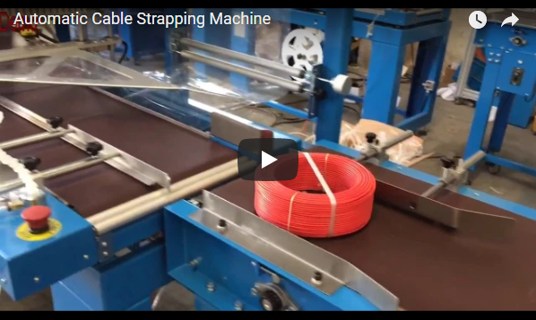
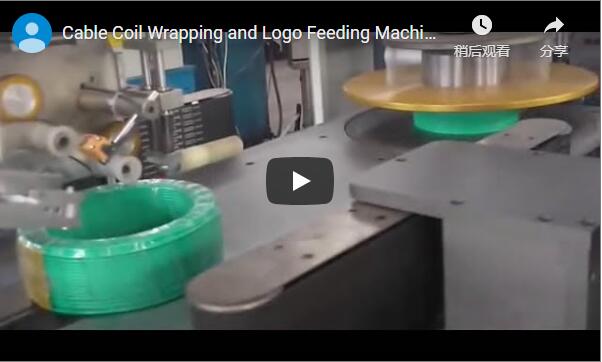
Executive summary: An automated continuous line for cable winding, coiling, strapping, heat shrinking, and robotic palletizing relies entirely on synchronous material transfer. A disruption at any single station creates an immediate line buffer failure. This technical advisory examines the functional integration of each module—from infeed stabilization to mechanical robotic palletizing—and defines the empirical benchmarks, safety engineering standards, and kinematic checkpoints required to validate a fully automated packaging installation prior to capital procurement.
Table of Contents
- What this page helps you decide
- Why the steps must stay in sequence
- How the line moves a bundle
- How the robot stacks the coil
- What the safety picture shows
- What the line operation demonstrates
- Buyer’s verification checklist
- FAQ
- Related reading
- Next step
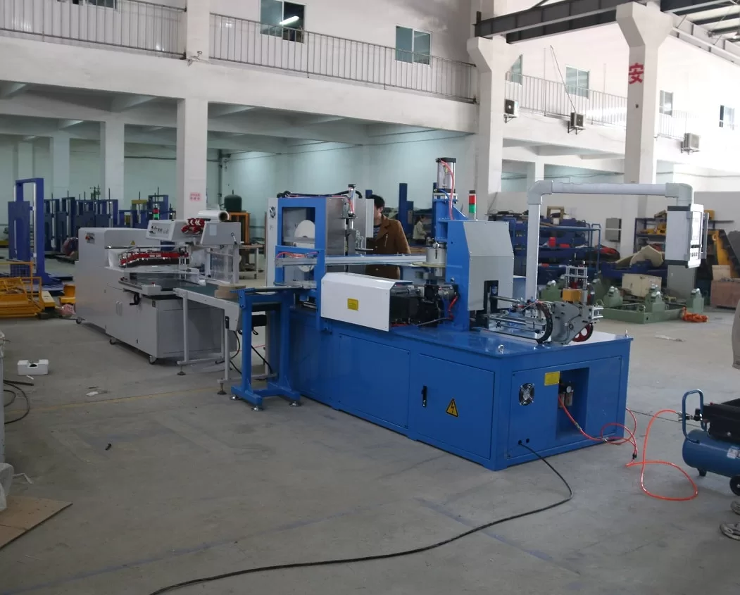
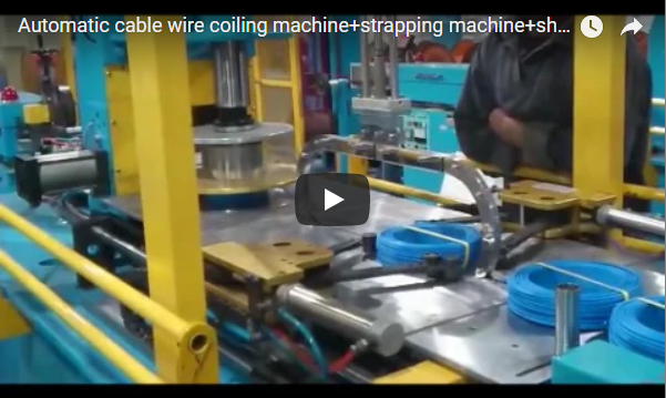
Caption: Automatic dual-head cable winding and coiling station with continuous tension feedback.
What this page helps you decide
An automated industrial line integrating cable coiling, binding/strapping, thermal film packaging, and robotic stacking is evaluated on continuous transfer capability. Each module must execute its mechanical cycle and transfer the coiled product to the next station within a synchronized takt time. Without precise inter-station handshaking, a multi-stage packaging line operates merely as isolated machines linked by passive conveyors.
This guide provides technical criteria for factory directors and packaging engineers evaluating automated cable packaging lines. It reviews module transitions, clarifies the mechanical reality of automated coil handling, highlights critical boundary conditions that brief machine footage cannot demonstrate, and provides the engineering verification criteria necessary before signing procurement specifications.
Why the steps must stay in sequence
Cable coil packaging requires strict physical sequence adherence because each downstream operation relies on the structural integrity established by the preceding step:
- Coiling and Metering: The cable must be wound under controlled dynamic tension to maintain uniform inner diameter (ID) and outer diameter (OD) geometry.
- Radial Binding/Strapping: PP or PE strapping bands must secure the core immediately to prevent memory-induced expansion (elastic spring-back) once released from the coiling spindle.
- Film Enclosure and Thermal Shrinkage: The banded bundle is wrapped with polyethylene (PE) or polyolefin (POF) film and passed through a heat chamber. Thermal shrinkage creates a compact, dustproof, and moisture-resistant barrier that holds loose wire ends firmly in place.
- Palletizing: The stabilized, dimensionally consistent coil is transferred by an articulated industrial robot into preset palletizing matrices.
[Raw Cable Feed]
       │
       ▼
[Precision Coiling] ──(Tension Control)──► [Radial Strapping]
                                                   │
                                                   ▼
[Robotic Palletizing] ◄──(Conveyor Handshake)─── [Film Shrink Tunnel]
Any breakdown in sequence causes process failure. If strapping tension fluctuates, coil geometry deforms, causing jamming inside the thermal shrink tunnel. If shrinking is uneven or under-cured, robotic mechanical grippers risk tearing the film or displacing coils during pallet placement.
How the line moves a bundle
The transfer line uses low-friction motorized flat-belt conveyors and pneumatic lateral positioning gates to advance ring-shaped cable coils through successive processing zones:
- Infeed Alignment: Coiled and strapped cable rings arrive horizontally (eye-to-sky orientation) on the primary transfer belt. Side guide rails with low-friction polymer liners center the bundle relative to downstream tooling.
- Indexing Station: The coil transfers through a centering module equipped with motorized vertical guide rollers. Here, pneumatic index stops arrest forward travel for registration before entering the wrapping and heat zone.
- Thermal Processing Station: A thermal hood equipped with internal blowers and heating elements encloses the moving bundle. Controlled heated air circulation (typically 140°C to 180°C depending on film micron gauge) shrinks the outer polyolefin casing snugly around the cable perimeter. Fume evacuation ports extract thermal vapors to keep the transfer zone clear.
- Discharge Staging: The stabilized coil exits the heat chamber and indexes onto a machined steel pick-up table. Optical diffuse-reflective sensors verify bundle presence, orientation, and clearance before signaling the palletizing cell.
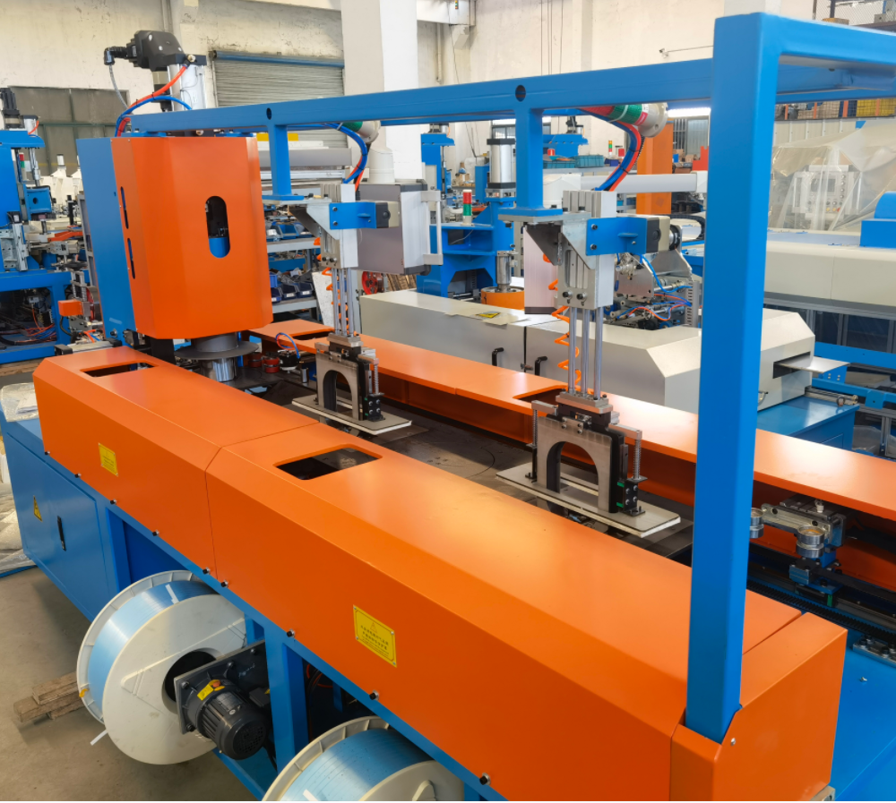
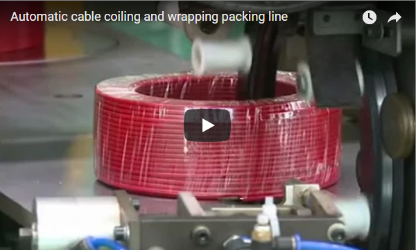
Caption: Inline cable traversing, binding, and conveyor transfer staging.
How the robot stacks the coil
The palletizing cell uses an industrial 6-axis articulated robot configured for high-repeatability material handling.
- End-of-Arm Tooling (EOAT) Mechanics: Coiled cable bundles have central through-holes, uneven top surfaces, and elastic tension under the packaging film. Standard vacuum suction cups cannot maintain reliable seal integrity on these irregular surfaces. Instead, the robot utilizes a specialized pneumatic internal-expanding mechanical gripper (or dual-action perimeter clamp). The expanding finger mechanism enters the coil eye, exerts controlled radial holding force against the inner core, and secures the bundle without crushing the cable insulation.
- Palletizing Matrix Execution: The robot lifts the coil from the staging table, rotates smoothly through its travel arc, and lowers the coil into programmed pallet coordinates inside the safety cell.
- Stack Formation: Bundles are stacked in multi-layer nested columns or interlocking brick patterns. The PLC tracks layer counters, pallet presence sensors, and height offsets to ensure consistent vertical alignment up to targeted limits (typically 1,200 mm to 1,500 mm total stack height).
What the safety picture shows
Industrial packaging cells combining high-speed indexing conveyors, high-temperature thermal enclosures, and multi-axis articulated robots require multi-layer safety integration complying with ISO 12100 and ISO 10218-2 standards.
- Robotic Cell Guarding: The robot workspace is fully enclosed by industrial perimeter wire-mesh fencing. Interlocked access doors prevent human intrusion during automatic cycles, triggering Category 4 / PLe safe-stop protocols if breached.
- Visual Status Indication: Integrated stack signal towers (Green: normal automatic cycle; Amber: buffer starved/full; Red: emergency stop or safety breach) provide continuous system status visibility.
- Critical Items Requiring Supplier Clarification:
- Thermal Tunnel Enclosure: Verify that the hot-air shrink station incorporates double-walled thermal insulation, finger-safe entry/exit tunnels, and mechanical heat baffles complying with EN 415-6.
- Conveyor Pinch Points: Verify physical underside nip guards and optical muting light curtains where coils cross physical cell boundaries.
- E-Stop Distribution: Ensure accessible dual-channel emergency stop buttons are placed at every manual intervention point, including winding heads, strapping dispensers, and pallet discharge conveyors.
What the line operation demonstrates
Visual demonstrations confirm foundational mechanical functionality, but engineering buyers must differentiate demonstrated capabilities from unverified parameters:
- Demonstrated Capabilities:
- Smooth motorized flat-belt conveying with steady coil orientation control.
- Integrated heat application that achieves snug film shrinkage across the coil circumference.
- Continuous, repeatable picking and placing of packaged coils via 6-axis robotic arm with rigid mechanical gripping.
- Segregated physical cell perimeter guarding around the high-speed palletizing envelope.
- Parameters Requiring Contractual Verification:
- Complete Line Takt Time: Continuous cycle time per coil across all four stages combined.
- Upstream Coiling & Strapping Rates: Wire traversing precision, cutting accuracy, and radial strap tension control.
- Dimensional Range Flexibility: Maximum and minimum coil OD, ID, and height limits handled on the same conveyor tooling without manual changeover.
- Thermal Tunnel Specifications: Installed kW capacity, operating temperature stability, and thermal air velocity control.
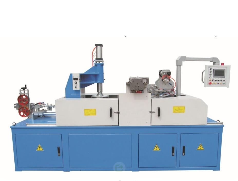
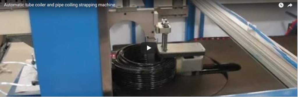
Caption: Fully automatic cable winding and coiling system with integrated tie station.
Buyer’s verification checklist
Use this matrix during equipment tendering to ensure all functional performance criteria are contractually specified:
| Engineering Parameter | Supplier Data Required | Procurement Impact |
|---|---|---|
| Full Cycle Takt Time | Clocked run from uncoiled wire to final pallet placement | Prevents line bottlenecking when upstream extruders run continuously. |
| Coil Size Range | Min/Max OD (mm), ID (mm), and Coil Height (mm) | Confirms tooling versatility across complete product SKUs. |
| Coil Weight Range | Minimum and maximum payload capacity (kg) | Defines robot payload sizing and conveyor drive motor longevity. |
| Film & Heat Specs | Film type (PE/POF), gauge (µm), tunnel kW, and temp window (°C) | Controls consumable cost, electrical consumption, and wrap quality. |
| EOAT Gripper Design | Internal ID expansion stroke, clamp force (N), and contact padding | Prevents jacket scuffing or bundle drop failures during acceleration. |
| Safety Integration | Performance Level (ISO 13849-1), interlock ratings, LOTO architecture | Ensures factory floor compliance with OSHA and CE Machinery Directives. |
Technical Verification Submittal Requirements
Request that your equipment supplier provide the following documentation alongside formal price quotations:
- Complete layout drawing (CAD / DWG) showing electrical drop points, pneumatic supply (0.6–0.8 MPa), and total footprint.
- Uncut video documentation demonstrating continuous, unassisted operation through 20+ sequential coil cycles.
- Consumable specifications: strapping band grade, breaking strength, film width, and thickness requirements.
- PLC architecture specification (e.g., Siemens S7-1500 / Rockwell GuardLogix) with complete I/O assignment mapping.
FAQ
How does the robot end-effector secure the cable coil during high-speed transfer?
Articulated palletizing robots handling hollow cable coils use pneumatically actuated internal-expanding grippers or synchronized three-jaw clamp mechanisms. The tooling centers itself inside the coil core (ID) and applies outward expansion force against the inner diameter while external support fingers stabilize the bottom, eliminating vacuum suction failures on uneven wrap surfaces.
What causes film splitting or loose tails inside the shrink tunnel?
Film splitting usually stems from excessive tunnel temperatures, uneven convective airflow, or mismatched film gauge. Loose tails occur when the film sealing bar cut temperature is too low or dwell time is insufficient. A properly configured line includes independent PID temperature controls for both the sealing bar and the shrink chamber recirculating fan.
Can this packaging line accommodate varying cable coil diameters automatically?
Yes, modern lines accommodate diverse coil sizes within specified geometric envelopes (e.g., OD 200 mm to 500 mm). Tooling adjustments utilize recipe-driven servo drives for conveyor width guides, coil index stops, and robot coordinate shifts selected directly from the main HMI.
Related reading
- Cable winder — automated continuous winding and spooling equipment.
- Automatic coiling machine — specialized coiling and tying machines for wire and cable.
- Automatic strapping machine — radial and circumferential strapping systems.
- Shrinking machine — industrial heat shrink tunnels and thermal packaging systems.
- Motion sealer — high-speed continuous film sealing units for packaging lines.
- Automatic packing line — complete end-of-line turn-key packaging solutions.
Next step
To evaluate an automated winding, coiling, strapping, shrinking, and robotic palletizing line for your specific wire or cable products:
- Provide your complete cable specification matrix: core cross-sections, finished coil minimum/maximum dimensions (OD × ID × Height), bundle weight ranges, and target coils-per-hour throughput.
- Request a formalized plant layout simulation illustrating conveyor buffering, thermal dissipation clearance, and robotic safety zones.
- Submit your inquiry and schedule a technical conference via our engineering consultation gateway at the contact page.
Last reviewed: 2026-09-28
Published: 2026-09-28