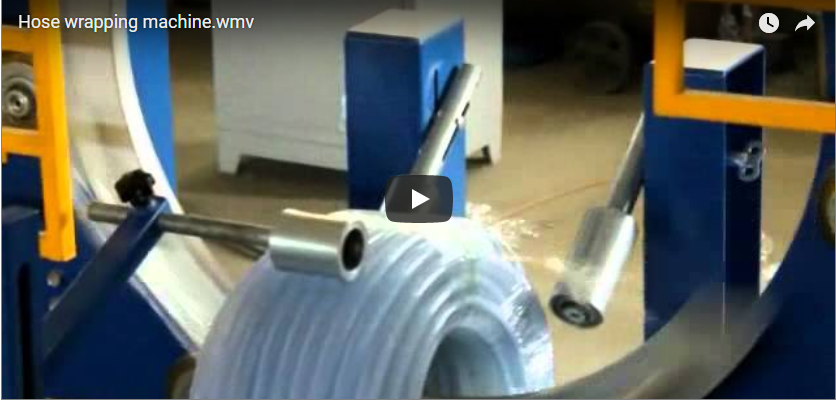
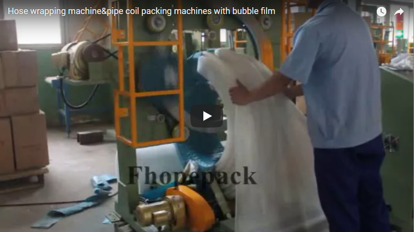
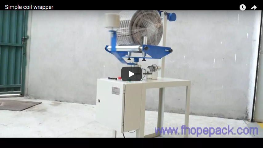
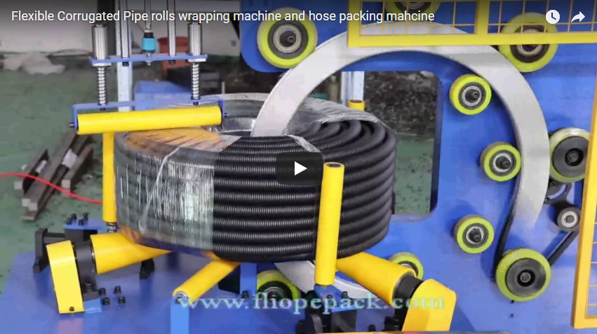
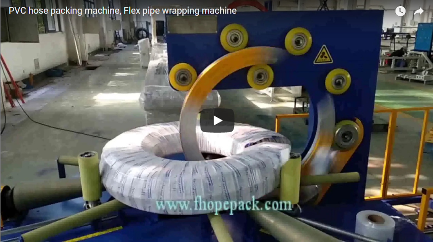
Executive Summary: In industrial coil packaging, “full coverage” is an operational specification rather than a universal machine capacity. True surface containment—across the inner bore (ID), outer diameter (OD), and both side faces—requires precise mechanical clearance for the shuttle carriage, calibrated advance pitch accounting for film neck-down, and rigorous continuous-tension control. This technical engineering guide breaks down the physical boundaries between envelope sizing, kinematic overlap verification, and material yield testing, providing procurement engineers and plant managers with a field-tested protocol to specify, inspect, and commission through-eye orbital wrapping systems without operational interference or catastrophic transit corrosion.
Turn “Full Size” into Two Clear Requirements
For an industrial coil wrapper, the sales claim of “full size” often conceals severe application mismatches. To establish true technical feasibility, the engineering team must split this vague phrase into two distinct, non-negotiable specifications:
- The Product Envelope Boundary: Inner diameter (ID), outer diameter (OD), axial face width, and total coil weight. These values must never be quoted as isolated extrema. A machine that handles a 2,000 mm OD on a light wire reel cannot necessarily support a 2,000 mm OD heavy steel coil that exceeds the radial bearing ratings of the support rollers. Always provide actual operational matrix combinations (e.g., minimum ID paired with maximum axial width; maximum OD paired with maximum mass).
- The Finished Package Specification: The target surfaces requiring physical barrier protection (inner bore, outer circumference, side flanks), nominal layer count, allowable seam overlap, and mechanical tail-retention criteria.
       [Top Stabilizer / Pressure Roller]
                    ▼
           .-----------------.
          /   Coil OD Face    \
         |  .-'`````````'-.   |
         | /   Coil Bore   \  |   ◄--- [Rotating Shuttle / Ring Path]
         | |   (ID Space)  |  |        (Carriage clearance must account
         | \               /  |         for radial coil deflection)
         |  '-._________.-'   |
          \   Coil OD Face    /
           '-----------------'
              ▲             ▲
         [Support A]   [Support B]  ◄--- Driven Support / Turning Rollers
Specifying bore and flank coverage is far more actionable than demanding “complete export protection.” It forces the machine builder to map the exact trajectory of the material dispensing head through the eye of the coil.
Furthermore, surface coverage alone does not guarantee structural load containment, vapor barrier performance, or corrosion resistance. Stretch wrap provides surface cohesion and dustproofing; it cannot replace steel strapping bands on spring-tempered slit coils. Incoming coil conditions—including upstream banding integrity, transport orientation (eye-to-sky vs. eye-horizontal), and overhead crane rigging—must be documented as explicit system inputs rather than expecting the wrapper to stabilize an unbanded, loose load.
Check the Through-Eye Path and the Support Arrangement Together
In through-eye orbital wrapping, the rotating ring carries the film carriage through the hollow core of the coil while two driven support rollers rotate the coil around its horizontal axis. Synchronization of these orthogonal motions generates a continuous toroidal wrap.
+-----------------------------------------------------------------------------------------+
|                              THROUGH-EYE CLEARANCE ENVELOPE                             |
|                                                                                         |
|       ( ( (  Ring Structure  ) ) )                                                      |
|     ================================                                                    |
|           |     Carriage     |                                                          |
|           |  Width (W_carr)  |                                                          |
|           +------------------+                                                          |
|     ================================                                                    |
|                   │                                                                     |
|            Clearance (C_min) ≥ 50 mm                                                    |
|                   ▼                                                                     |
|           .──────────────────.                                                          |
|          /                    \                                                         |
|         |    Minimum Coil      |  ==> Check:                                            |
|         |      Bore (ID)       |      ID_min ≥ W_carr + T_ring + 2 × C_min              |
|          \                    /                                                         |
|           '──────────────────'                                                          |
+-----------------------------------------------------------------------------------------+
A common failure mode in coil wrapper commissioning is treating the nominal coil ID as available machine clearance. The ring frame has a defined cross-sectional thickness (T_ring), but the critical dimension is the dynamic swept path of the cantilevered material carriage (W_carr), its tension brake assembly, and the film roll diameter.
The clearance condition must satisfy the dynamic boundary inequality:
ID_min ≥ W_carr + T_ring + 2 × C_min
Where dynamic clearance C_min must be at least 50 mm to absorb coil eccentricity, telescoping edges, and roller tracking runout.
Procurement teams must demand a formal 3D layout drawing showing the physical dispenser passing through the smallest quoted bore. Concurrently, inspect the lower support rollers. Small-diameter, narrow coils sit lower between the rollers, drastically lowering their bore centerline relative to the ring center; wide, large-OD coils sit high. The machine must incorporate motorized vertical ring adjustment (or dynamic roller-lift geometry) to ensure the center of the ring aligns with the variable cross-sectional center of the coil wall.
Verify structural utilities from official equipment proposals rather than assuming specifications across product lines. For instance, wire-coil wrappers such as the FHOPE FPW-300 utilize distinct drive ratios and clamping dynamics compared to heavy-duty FPS steel-strip wrappers; air consumption, pneumatic clamping pressure (typically 0.5–0.7 MPa), and motor sizing cannot be cross-extrapolated.
Use Outer-Diameter Overlap as a Setup Check, Then Inspect Every Surface
Overlap geometry on a toroidal wrapper is inherently non-uniform. Because the linear travel distance per ring cycle is longest at the outer circumference and shortest at the inner bore, the film overlap percentage reaches its minimum at the OD:
Overlap_OD = 1 - (π × D_coil × ω_support) / (W_effective × ω_ring)
Where:
D_coil= Outer diameter of the coil (mm)W_effective= Actual applied film width on the load (mm)ω_support= Rotational speed of the support rollers (RPM)ω_ring= Rotational speed of the wrapping ring (RPM)
[ Inner Bore (ID) ]  =======================================>  Overlap: 60% - 75%
                                                               (Tightly packed layers)

[ Side Flanks ]      ============================>              Overlap: 40% - 55%
                                                               (Intermediate density)

[ Outer Face (OD) ]  ====================>                      Overlap: Minimum 25% - 30%
                                                               (Critical boundary zone)
Because film narrows under tension—a phenomenon known as transverse neck-down—a nominal 500 mm roll pre-stretched at 200% will neck down to an effective width (W_effective) of only 360–400 mm at the coil surface. If the operator configures the advance pitch based on a nominal 500 mm width, the outer circumference will suffer from skipped passes and exposed metal.
Multi-Surface Quality Inspection Protocol
| Surface Zone | Primary Mechanical Vulnerability | Quality Inspection Checkpoint |
|---|---|---|
| Inner Bore (ID) | Film wrinkling, carriage scuffing, bunched tails | Check for continuous lamination without tears caused by tight radius turns. |
| Bore-to-Face Edges | Puncture from sharp coil slit edges, tension tear | Inspect for localized edge splitting; verify pre-stretch relief settings. |
| Outer Flanks | Uneven tracking, layer slippage during handling | Confirm uniform overlap pitch and consistent visual opacity across both faces. |
| OD Crown | Insufficient overlap (< 25%), seam separation | Verify that minimum overlap meets target across the entire 360° circumference. |
| Cut & Clamp Seam | Film tail peeling, welding failure | Ensure pneumatic clamp/heater or mechanical wipe-down holds against air transit. |
Keep a Geometric Estimate Separate from Roll Consumption
Estimating packaging material based purely on surface geometry yields an idealized theoretical consumption, not an operational bill of materials. The geometric wrapping path follows the toroidal cross-section:
Path_cycle ≈ 2 × (Coil_OD - Coil_ID) / 2 + 2 × Coil_Width = (Coil_OD - Coil_ID) + 2 × Coil_Width
Multiplying Path_cycle by the number of calculated passes gives the net applied length. However, this figure cannot be directly converted to purchased linear film without factoring in:
- Pre-stretch Ratio: A powered pre-stretch carriage operating at a 2.5:1 gear ratio (150% elongation) or 3:1 ratio (200% elongation) significantly reduces raw roll unwind length.
- Secondary Neck-down Mass Loss: Thinning cross-sections require higher layer counts to achieve equivalent moisture vapor transmission rates (MVTR).
- Process Waste: Film consumed during initial clamp anchoring, start-up revolutions, multi-layer reinforced edge wraps, and cut-tail trim losses.
+-----------------------------------------------------------------------------------------+
|                           CONSUMPTION CONVERSION PIPELINE                               |
|                                                                                         |
|  [ Net Toroidal Geometry ]                                                              |
|             │                                                                           |
|             ▼                                                                           |
|  [ Applied Film Length ]  ──( Divide by Pre-stretch: 1 + Ratio )──►  [ Unwind Length ]  |
|                                                                             │           |
|                                                                             ▼           |
|  [ Gross Purchased Roll Mass ]  ◄──( Add: Reinforcement Passes + Clamping Tail Losses ) |
+-----------------------------------------------------------------------------------------+
When switching wrapping media from conventional LLDPE stretch film to heavy HDPE woven fabric, VCI creep paper, or composite barrier foil, these kinematic assumptions shift:
- Woven tape and VCI kraft paper exhibit virtually zero elasticity (elongation < 5%); pre-stretch rollers must be disengaged or converted to surface-driven passive let-off with sensitive magnetic powder brake tensioning.
- Rigid non-stretch materials wrinkle severely on the inner radius if the tape width exceeds the turning radius limits of the coil ID.
- Mechanical cut-and-clamp units calibrated for thin stretch film will fail to shear high-tensile 120 GSM woven polypropylene without hardened, serrated pneumatic blade modifications.
Send an RFQ Organized Around the Package and the Work Sequence
To eliminate supplier ambiguity and avoid undersized machinery, industrial procurement packages should center on an engineering schedule rather than broad production descriptions:
========================================================================================
                         TECHNICAL RFQ DATA ENTRY MATRIX
========================================================================================
1. INCOMING COIL SCHEDULE:
   - Dimensions: ID min/max [mm] | OD min/max [mm] | Width min/max [mm]
   - Mass: Minimum / Maximum weight [kg]
   - Substrate: Hot-rolled / Cold-rolled steel / Copper / Wire rod bundle
   - Upstream Restraint: Bare / Strapped (radial/circumferential) / Deburred edges

2. FINISHED PACKAGE SPECIFICATION:
   - Surfaces Covered: Complete ID / OD / Both side flanks / Outer crown only
   - Overlap Criteria: Minimum OD overlap percentage (e.g., ≥ 35%)
   - Barrier Layering: Single layer / 1-layer VCI paper + 1-layer PE film outer jacket
   - Tail Anchoring: Mechanical tuck / Pneumatic clamp-and-seal / Adhesive tape wipe

3. CONSUMABLE SCHEDULE:
   - Primary Material: LLDPE Stretch Film / Woven PP Fabric / Reinforced VCI Paper
   - Roll Geometry: Core ID [mm] | Outer roll OD max [mm] | Nominal film width [mm]
   - Film Gauge: Thickness [µm] | Target pre-stretch percentage [%]

4. TACT-TIME & WORK SEQUENCE BOUNDARIES:
   - Target Line Output: Coils per hour (gross including handling)
   - Scope of Wrapper Cycle: Auto-centering -> Wrap cycle -> Auto-cut -> Eject
   - Interface Architecture: Crane loading / C-hook / Upender / Walking-beam conveyor

5. DOCUMENTATION & ACCEPTANCE REQUIREMENTS:
   - Mechanical 3D clearance envelope drawing for smallest bore
   - Factory Acceptance Test (FAT) protocol utilizing actual client test coils
========================================================================================
Nominal “coils-per-hour” ratings must be verified by auditing the entire sequence time: loading, positioning, film attachment, wrapping, cutting, wipe-down, and unloading.
Review Access and Maintenance Before Agreeing the Operator Tasks
The through-eye wrapping ring is a Class-4 mechanical hazard. The convergence of a high-speed rotating ring through a hollow core with adjacent driven support rollers creates severe pinch and shear zones. Operational safety requires robust adherence to international machinery standards.
       [ Physical Perimeter Safety Fencing (EN ISO 14120) ]
  +------------------------------------------------------------+
  |                                                            |
  |     [ Optical Safety Light Curtain (IEC 61496 Type 4) ]    |
  |               │                                            |
  |               ▼                                            |
  |       ====================                                 |
  |      [  ORBITAL WRAPPER  ] <--- Pneumatic Rod Clamping     |
  |      [   HAZARD ZONE     ]      System on Vertical Ring    |
  |       ====================      Counterweight (EN ISO 13849)|
  |                                                            |
+------------------------------------------------------------+- Risk Mitigation (ISO 12100 & EN 415-5): Wrappers must integrate fixed perimeter guards conforming to ISO 14120, interlocked with dual-channel safety switches. Loading stations exposed to overhead crane access must feature Type 4 safety light curtains (IEC 61496) integrated via a certified safety PLC controller (EN ISO 13849-1, PL d/Cat 3 minimum).
- Gravity Drop Prevention: Vertical moving rings must incorporate mechanical drop-stop pawls or pilot-operated rod locking brakes to eliminate suspended load drop hazards during maintenance or drive belt severance.
- Zero Energy State (LOTO): Maintenance tasks—including film carriage re-threading, roll loading, and cutter blade adjustment—require immediate, verified isolation of power and compressed air. Exhaust valves must dump stored pneumatic pressure in accordance with OSHA 1910.147 and HSE mechanical safety guidelines. Emergency-stop pushbuttons must never be used as a substitute for true mechanical Lockout/Tagout.
Demonstrate Coverage on Identified Coils Before Accepting the Setup
Final equipment sign-off should depend on physical Factory Acceptance Testing (FAT) using predefined worst-case product configurations, rather than arbitrary test cylinders.
========================================================================================
                       FACTORY ACCEPTANCE TRIAL TEST RECORD
========================================================================================
Client: ___________________________            Date: __________________________________
Machine Model: ____________________            Serial Number: _________________________

[TEST LOAD A: MINIMUM BORE / MAXIMUM WIDTH]
- Measured Coil Parameters: ID: _____ mm | OD: _____ mm | Width: _____ mm | Weight: _____ kg
- Material Used: Type: _____________ | Gauge: _____ µm | Measured Neck-down Width: _____ mm
- Carriage Clearance: Measured dynamic through-bore clearance: _____ mm (Pass ≥ 50 mm)
- Overlap Verification:
  * Bore Overlap (ID): _____ %  |  Flank Overlap: _____ %  |  Outer Crown (OD): _____ %
- Target Defect Check: [ ] Zero edge punctures  [ ] Zero window exposure  [ ] Tail secure

[TEST LOAD B: MAXIMUM WEIGHT / MAXIMUM OD]
- Measured Coil Parameters: ID: _____ mm | OD: _____ mm | Width: _____ mm | Weight: _____ kg
- Roller Drive Status: [ ] Smooth tracking  [ ] Zero slippage  [ ] Roller motor Amps: _____ A
- Total Cycle Time: Loading: ___s | Wrapping: ___s | Cut/Clamp: ___s | Total: ___s
- Total Material Consumed: Net mass used: _______ kg | Calculated vs. Actual Variance: ____ %

Sign-off Authority (OEM Lead Engineer): ___________________   Date: ____________________
Sign-off Authority (Client Lead Auditor): ___________________   Date: ____________________
========================================================================================
Document both passing and unverified product sizes. If post-commissioning variations arise—such as transitioning from 25 µm standard stretch wrap to 100 GSM woven packaging—a complete re-audit of overlap and cutting dynamics is mandatory.
For custom application reviews, project schedules, and clearance layout verifications, send your detailed coil matrix and process line parameters to the FHOPE engineering group at info@fhopepack.com. Reference the accompanying technical operation video to ground all technical discussions in specific, field-proven mechanical configurations.