Executive summary
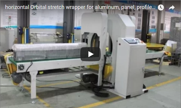
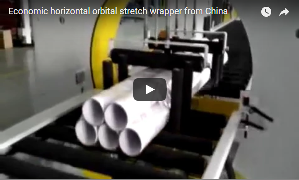
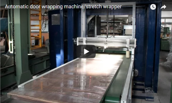
Oversized, elongated, and non-palletized cargo—including architectural panels, composite boards, pre-assembled furniture, and structural insulation frames—cannot be stabilized on conventional vertical pallet turntables without severe overhanging or tip-over hazards. A horizontal orbital stretch wrapper transports the workpiece through a continuously driven rotating ring on an automated roller conveyor, applying high-tension LLDPE film across all four longitudinal faces while the load remains statically seated. The heavy-duty E1400 platform accommodates rigid workpieces from 1,000 to 3,000 mm in length, widths up to 1,400 mm, and cross-sectional heights up to 1,000 mm, operating at variable ring speeds between 10 and 60 r/min.
Table of Contents
- Why Heavy and Bulky Loads Require Orbital Wrapping
- Size Window & Envelope Sizing: Will Your Object Fit?
- Kinematics: Film Pitch, Consumption, and Cycle Calculations
- Infeed and Outfeed Conveyor Dynamics & Product Stabilization
- Engineering Selection Checklist
- Safety Compliance: EN 415-10 and ISO 12100 Standards
- Engineering FAQ
- Factory Acceptance & Technical Inquiries
- Related Systems & Further Reading
- Standards & Sources
Why Heavy and Bulky Loads Require Orbital Wrapping
Wrapping oversized or elongated products on standard vertical rotating platforms introduces dynamic instability, load shifting, and structural damage. The orbital wrapping process isolates rotational momentum within a balanced structural ring, ensuring the payload travels along a continuous linear axis without centrifugal disturbance.
| Turntable Limitation | Orbital Stretch Wrapper Engineering Solution |
|---|---|
| Overhanging Cantilever | Workpiece rests flat on powered rollers; product length determines throughfeed cycle rather than footprint. |
| Centrifugal Unbalance & Tipping | Workpiece advances linearly along the conveyor center line; the aluminum orbital ring revolves around it. |
| Unprotected Longitudinal Surfaces | Dual or single film rolls wrap continuously around top, bottom, and side faces in an overlapping helix. |
| Edge Crushing & Deformation | Pneumatic film brake or motor-driven variable pre-stretch adjusts wrapping force per load recipe. |
| Inconsistent Manual Film Usage | PLC-controlled overlapping (10% to 90%) ensures calibrated containment force on every production cycle. |
Size Window & Envelope Sizing: Will Your Object Fit?
Machine sizing requires verifying both the linear cross-section and the rotating diagonal clearance against the inner ring diameter. The maximum diagonal dimension is:
Diagonal = √(Width² + Height²)
The internal ring diameter must clear this diagonal plus the dynamic intrusion envelope of the orbital film carriage (typically requiring a radial safety margin C ≥ 150 mm).
         ┌────────────────── Ring ID ──────────────────┐
         │                                             │
    ┌────┼──────────────── Film Carriage ─────────────┼────┐
    │    │                 Dynamic Travel              │    │
    │    │        ┌─────────────────────────┐          │    │
    │    │        │ Workpiece Cross-Section │          │    │
    │    │        │       (W × H)           │          │    │
    │    │        │  Diagonal = √(W² + H²)  │          │    │
    │    │        └─────────────────────────┘          │    │
    │    │                                             │    │
    └────┼─────────────────────────────────────────────┼────┘
         │                                             │
└─────────────────────────────────────────────┘| Specification Parameter | E1400 High-Capacity Wrapper | E1000 Medium-Capacity Wrapper |
|---|---|---|
| Max Workpiece Length | 1,000–3,000 mm (Custom extensions available) | Over 1,000 mm |
| Max Load Cross-Section (W × H) | 1,400 mm W × 1,000 mm H | Bundle Outer Diameter: 400–1,000 mm |
| Diagonal Clearance Envelope | Up to 1,720 mm diagonal | Up to 1,080 mm diagonal |
| Payload Capacity | 500–2,500 kg (Matched to conveyor drive) | 50–400 kg |
| Ring Rotation Speed | 10–60 r/min (VFD controlled) | 10–60 r/min (VFD controlled) |
| Film Roll Specification | Width: 300 mm or 500 mm; OD ≤ 250 mm | Width: 100–500 mm; OD ≤ 250 mm |
| Total Drive Power | Approximately 4.5–7.5 kW | Approximately 4.5 kW |
Engineering Sizing Check: A product measuring 2,000 mm L × 1,200 mm W × 900 mm H yields a cross-sectional diagonal of √(1,200² + 900²) = 1,500 mm, running safely inside the E1400 clearance envelope. Conversely, an object measuring 1,500 mm L × 1,100 mm W × 1,050 mm H exceeds the 1,000 mm structural height limit and risks colliding with the carriage frame, requiring an upsized ring chassis. All irregular profiles must be evaluated at their widest protruding geometries, including packaging battens, runner skids, and protective dunnage.
Kinematics: Film Pitch, Consumption, and Cycle Calculations
The horizontal forward speed of the conveyor and the rotational speed of the ring govern the pitch and overlap of the stretch film.
Film Pitch = Film Width × (1 - Overlap Ratio)
Linear Conveyor Speed = Film Pitch × Ring Rotational Speed
Below is a reference kinematic calculation for a 2,000 × 1,200 × 900 mm payload wrapped using 500 mm wide film at a 50% overlap setting:
| Kinematic / Material Parameter | Governing Equation | Verified Result |
|---|---|---|
| Linear Film Pitch | 500 mm × (1 – 0.50) | 250 mm per turn |
| Body Revolutions | 2,000 mm ÷ 250 mm/rev | 8 full revolutions |
| Reinforcement Turns | Front buffer + Rear buffer | 1 Lead + 1 Tail (10 turns total) |
| Wrapped Perimeter | 2 × (1,200 mm + 900 mm) | 4.2 m per wrap |
| Applied Film Length | 10 turns × 4.2 m | 42 m (Relaxed on load) |
| Cycle Wrapping Duration | 10 turns ÷ 30 r/min | 0.33 min (≈ 20 seconds) |
| Synchronized Conveyor Speed | 0.25 m/turn × 30 r/min | 7.5 m/min |
Using 300 mm film on the identical payload reduces the pitch to 150 mm, requiring 14 body revolutions plus reinforcement (16 turns total). This increases cycle time to 32 seconds but yields higher localized containment force for multi-board timber stacks or high-density goods.
Infeed and Outfeed Conveyor Dynamics & Product Stabilization
To prevent payload deflection and ensure uniform tension, the workpiece must be continuously supported across the wrapping plane. The unsupported gap at the ring center is bridged by powered transition rollers, ensuring the film web does not bear gravity loads during rotation.
       [ Infeed Conveyor ]      [ Orbital Ring ]      [ Outfeed Conveyor ]
      ═════════════════════╦═══                 ═══╦═════════════════════
       ●   ●   ●   ●   ●   ║     ( O-Ring )    ║   ●   ●   ●   ●   ●
      ═════════════════════╩═══                 ═══╩═════════════════════
|<-- Length ≥ Object -->| |<-- Length ≥ Object -->|- Conveyor Geometry: The infeed and outfeed roller conveyors must each equal or exceed the maximum product length (e.g., minimum 3,000 mm for the E1400 platform).
- Transient Dynamic Control: Standard Siemens or Schneider VFDs manage controlled ramp-up (soft-start) and exact position-stop indexing via proximity encoders, keeping the ring oriented at the identical home angle for film tail clamp-and-cut cycles.
- Top Hold-Down & Lateral Constraint: Light, hollow, or high-aspect-ratio objects (such as structural foam, honeycomb core panels, or light furniture frames under 100 kg) risk shifting or uplifting due to tangential film tension. Pneumatic-actuated overhead hold-down rollers and adjustable lateral guide rollers maintain center-line tracking without marring finished surfaces.
- Pre-Stretch Carriage Systems: Motorized mechanical pre-stretch (150% to 250%) decouples containment tension from film unwinding drag, allowing delicate timber frames or fragile edge trims to be tightly bundled without localized corner crushing.
Engineering Selection Checklist
To finalize your orbital wrapper configuration, verify the following six mechanical parameters:
- Maximum & Minimum Workpiece Envelope: Width, height, length, and cross-sectional diagonal including all skids and skids/pallets.
- Payload Weight Range: Total mass per linear meter (determines roller wall thickness, shaft diameter, and gearmotor sizing).
- Surface Sensitivity: High-gloss lacquered panels, bare metals, or soft foams requiring polyurethane-coated rollers and cushioned pneumatic hold-downs.
- Wrapping Media: Standard LLDPE cast film (17–35 µm), VCI corrosion-inhibiting film, crepe paper, or woven PP banding.
- Throughput Requirements: Target parts per hour (determines single-roll vs. twin-roll ring carriage and conveyor transfer rates).
- Automation Level: Standalone manual placement with foot-pedal cycle start, or inline integration via dry-contact PLC handshakes with automated cut-and-wipe units.
Safety Compliance: EN 415-10 and ISO 12100 Standards
Industrial orbital wrappers fall under the harmonized European standard EN 415-10 (Safety of packaging machines: Wrapping machines), supported by system risk assessment conforming to ISO 12100:2010.
- Ring Guarding: The rotating ring, friction drive wheels, and transmission belts are enclosed within a heavy-gauge welded steel perimeter chassis with interlocking service access doors.
- Zone Safeguarding: Infeed and outfeed portals are secured via Type 4 optical safety light curtains positioned in accordance with ISO 13855 approach-speed calculations to prevent reach-in injuries during ring revolution.
- Emergency Stop Integration: Hardwired Category 0 / Category 1 emergency stop pushbuttons are integrated on the main HMI panel and external conveyor frames, immediately shedding ring kinetic energy through dynamic dynamic braking resistors.
- Pneumatic Isolation: LOTO-compliant residual pressure relief valves exhaust all stored pneumatic pressure to hold-down assemblies during maintenance interventions.
Engineering FAQ
Q: Does the cargo rotate during the wrapping process? A: No. The product advances in a purely linear path on powered roller beds while the balanced orbital ring revolves around it. This eliminates centrifugal load displacement, making it ideal for tall, unstable, or top-heavy cargo.
Q: What is the maximum load section the E1400 accommodates? A: The standard E1400 handles parts up to 1,400 mm in width and 1,000 mm in height, provided the overall cross-sectional diagonal does not exceed the effective internal ring clearance (nominal maximum diagonal: 1,720 mm). Profiles exceeding these dimensions require an upsized chassis (e.g., E1600/E1800).
Q: How do you prevent crushing on delicate panel corners? A: By utilizing a motorized power pre-stretch carriage. The film is elongated between two geared rollers prior to discharge, reducing residual elastic recovery force, while pneumatic top rollers provide balanced opposing restraint.
Q: How is lightweight product shifting prevented inside the ring? A: Low-mass components with high surface area (such as EPS blocks or light wooden casework) are stabilized using overhead pneumatic hold-down rollers and polymer side guide rollers that track along the conveyor center line.
Q: Can the equipment apply protective materials other than stretch film? A: Yes. The spindle core is compatible with LLDPE stretch film, VCI anti-rust barrier film, coated kraft paper, and woven polyethylene tape.
Q: What are the facility utility requirements? A: The electrical system requires 380–480V, 3-phase, 50/60 Hz (standard connected load 4.5–7.5 kW). Pneumatic components require clean, dry compressed air regulated between 0.5 and 0.8 MPa (5–8 bar).
Factory Acceptance & Technical Inquiries
- Submit Product Data: Send maximum dimensions, total weight, throughput targets, and product photos to info@fhopepack.com.
- Kinematic & Ring Sizing Audit: Our engineering team checks your cross-sectional diagonal envelope, confirms roller center pitch, and designs the film carriage layout.
- Quotation & Proposal Delivery: Receive a detailed functional specification, dimensional line drawing, and formal quotation within 24 hours.
Related Systems & Further Reading
- E1400 Horizontal Stretch Wrapping Machine (Product Specification)
- E1000 Horizontal Stretch Wrapping Machine (Product Specification)
- Industrial Horizontal Stretch Wrapping Systems for Sale
- High-Speed Horizontal Orbital Stretch Wrapper Video Guide
- Automated Horizontal Ring Stretch Wrapping Systems in Operation
Standards & Sources
- ISO 12100:2010 — Safety of machinery — General principles for design — Risk assessment and risk reduction.
- EN 415-10:2014 — Safety of packaging machines — Part 10: General requirements.
- ISO 13855:2010 — Safety of machinery — Positioning of safeguards with respect to the approach speeds of parts of the human body.
- FHOPE Packaging Systems — E-Series Orbital Stretch Wrapper Technical Documentation and Kinematic Guidelines.
Last reviewed: 2026-10-19