Executive summary
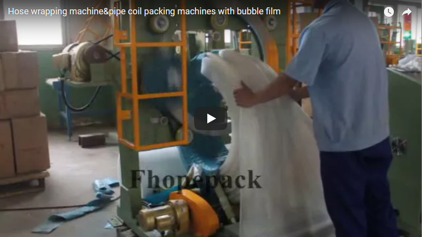
This technical guide addresses operations packaging coiled hydraulic hose, corrugated ducting, PVC tubing, and wire reels for transport. The machine analyzed is a semi-automatic eye-through orbital coil wrapping machine: an annular rotating ring drives packaging media through the coil core, while an operator manually loads the coil, feeds the film leading edge, and performs final cut-and-tuck sealing. While field demonstrations frequently deploy air bubble cushioning film for heavy-duty shock absorption, manufacturer standard baseline data sheets (such as the FPH-300N class) specify stretch film, with woven HDPE/kraft paper as engineered options. Before finalizing equipment orders, confirm kinematic envelope clearance, dispenser roll core dimensions, and mechanical safety interlocks in writing.
Table of Contents
- What this page helps you decide
- What a ring-style hose wrapping machine does
- Published specification: the FPH-300N class
- Bubble film versus stretch film
- The semi-automatic cycle, step by step
- What to verify before you buy
- Engineering observations: the semi-automatic interface in practice
- Buyer’s verification checklist
- FAQ
- Next step
- Related reading
- Sources
What this page helps you decide
Coiled hose packaging presents persistent material handling challenges: resilient memory causing radial spring-back, open hollow centers (“eyes”) prone to edge scuffing, and sensitive exterior jackets damaged by transit vibration. Loose hand-wrapping with cut film sheets leaves irregular voids, allowing friction damage and moisture penetration before reaching the end user.
Orbital ring wrapping solves this by applying continuous circumferential tension through the coil eye. This guide evaluates semi-automatic wrapping dynamics, establishing critical parameters to confirm with manufacturers: physical ring-to-coil envelope clearances, substrate compatibility across bubble and stretch materials, operator safety boundaries during manual feed cycles, and machine drive ratings. A structured technical verification matrix is included below for direct transmission to equipment vendors.
What a ring-style hose wrapping machine does
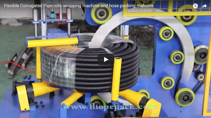
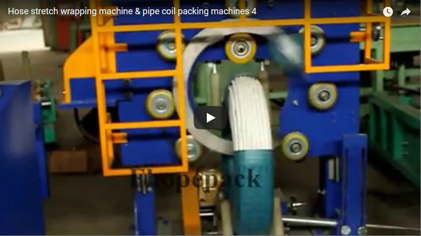
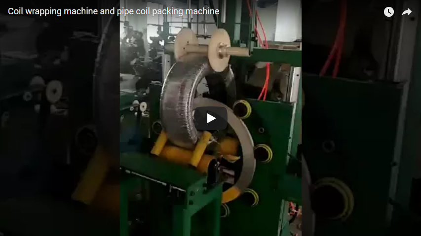
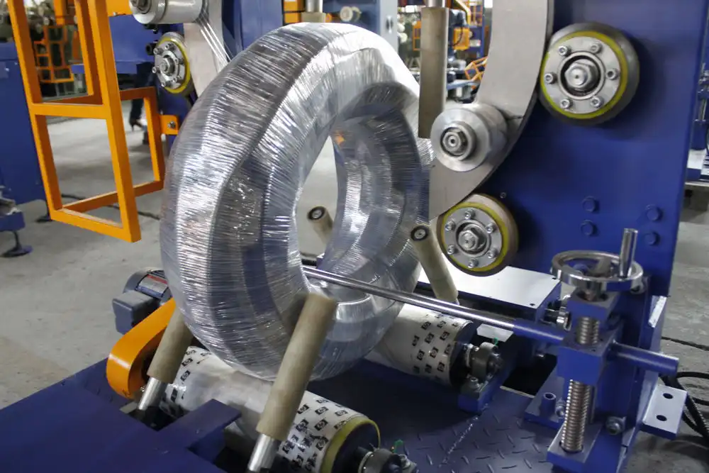
An eye-through hose wrapping machine rotates protective film rolls along a closed toroidal path, passing directly through the internal hollow core of a horizontally resting coil. As the main rotating ring turns, powered chassis support rollers simultaneously index the coil around its vertical axis, yielding a tightly overlapping, helical packaging layer over the entire cross-section.
In standard workshop configurations, the equipment comprises a welded structural steel base frame, perimeter impact-guard cages, twin polyurethane-sleeved load rollers, and an internal orbital drive ring driven by high-torque friction wheels. The operator manually loads the coil into the ring center, introduces the film tail to the coil surface under inching rotation, and allows the rotary ring to automate the continuous circumferential winding.
This division of labor balances capital cost and flexibility: high-torque rotational wrapping is automated to protect operators from repetitive strain, while coil positioning, initial film threading, and finishing rely on direct human oversight. This differentiates semi-automatic ring machines from fully continuous automated lines.
Published specification: the FPH-300N class
Operational setups of this type correspond to the industrial equipment category represented by the FPH-300N orbital hose wrapper. Actual production requirements must verify motor kw ratings, electrical ratings, and dimensional envelopes against vendor quotation data sheets. Standard published baseline specifications indicate:
| Engineering Parameter | Published Baseline Value (FPH-300N Class) |
|---|---|
| Machine Model Reference | FPH-300N |
| Coil Internal Diameter (ID) | Φ300–Φ700 mm |
| Coil Outer Diameter (OD) | Φ500–Φ1000 mm |
| Coil Width / Height Range | 100–300 mm |
| Maximum Load Capacity | 10–100 kg |
| Main Cycle Wrapping Speed | 23–35 s per coil (variable by overlap setting) |
| Maximum Rotational Speed of Ring | Up to 120 rpm (frequency inverter controlled) |
| Electrical Power Supply | 380 V, 50/60 Hz, 3-Phase, PE |
| Installed Power Rating | 1.9 kW |
| Standard Film Specification | LLDPE Stretch Film: Roll OD 100–180 mm, ID 50 mm, Width 90–100 mm (HDPE/Paper optional) |
The standard drive system utilizes variable frequency drives (VFD) allowing operators to regulate ring rotational speed and roller feed velocity, altering wrap overlap rates (typically 20% to 60%). Crucially, standard specification sheets list LLDPE stretch film, with paper or woven HDPE tape as options. Heavy air bubble cushioning film requires tailored tension assemblies and roll carriage clearances that must be confirmed explicitly during machine layout sign-off.
Bubble film versus stretch film
Material selection governs both transit survivability and wrapping mechanics. Standard LLDPE stretch film features high tensile memory (200%–300% elongation), consolidating the bundle into a moisture-sealed, rigid package. However, thin stretch films offer limited point-load dampening against transit impacts.
Air bubble film introduces closed cellular air pockets that isolate rigid hose fittings, ribbed spirals, and metal couplings from external shock. Because bubble wrap exhibits low tensile elongation (under 15%), it cannot be run through standard high-ratio pre-stretch roller carriages without cell rupture. Applying bubble wrap requires a mechanical friction brake dispenser capable of stable low-tension unwind (10–30 N).
For operations demanding both impact mitigation and moisture barrier sealing, specify a dual-ring or dual-carriage dispenser configuration. An inner layer of low-density bubble wrap applies impact cushioning, followed immediately by an outer wrap of LLDPE stretch film or woven HDPE tape to lock the envelope against dust, water spray, and scuffing.
The semi-automatic cycle, step by step
The operational cycle follows five coordinated mechanical steps:
- Load: The operator positions the coil onto the polyurethane drive rollers, aligning the hollow coil eye centrally with the rotating ring plane.
- Feed & Inching: The operator threads the film leading edge through the inner eye, pressing it against the coil OD. The operator activates low-speed ring inching to capture the film tail under its initial pass.
- Orbital Wrap: With the operator clear of the safety zone, the machine executes rotational wrapping at preset VFD speeds. Dual-axis motion (ring rotation plus roller indexing) applies the programmed overlap across the entire circumference.
- Tuck & Cut: The operator initiates cycle stop, isolates the ring, severs the material web manually, and smooths the film tail onto the coil flank.
- Secure & Unload: The film tail is sealed via self-adhesion or tape, and the wrapped coil is rolled onto downstream discharge gravity skids.
This semi-automatic arrangement eliminates the mechanical complexity and maintenance overhead of pneumatic clamp-and-cut mechanisms, making it suitable for moderate throughput facilities (25–40 coils/hour). However, overall line output depends on operator loading speed and ergonomics.

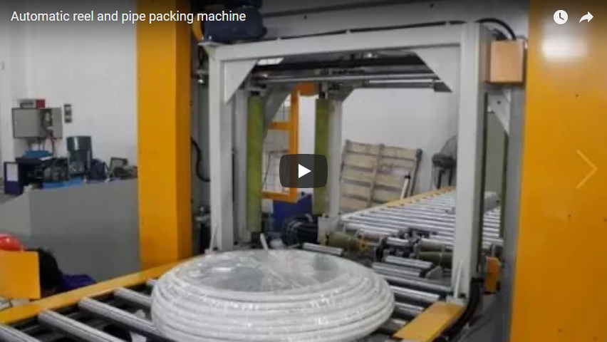
By comparison, fully automated wrapping systems integrate pneumatic auto-feed and mechanical cut-and-clamp grippers linked to optical sensors, removing manual film handling entirely. Plant engineers must weigh this automation investment against line cycle requirements.
What to verify before you buy
Field installations require thorough validation beyond basic catalog dimensions. Plant engineers should review seven critical engineering parameters prior to issuing purchase specifications:
- Toroidal Geometric Clearance: The coil core opening must satisfy geometric clearance criteria:
Coil Eye ID ≥ (Ring Radial Thickness + Film Carriage Outer Radius + 50 mm clearance)
Insufficient core opening causes high-speed collisions between the film carriage and the inner coil wall. - Material Tension Control: Ensure the unwind mandrel features adjustable mechanical friction brakes or magnetic particle clutches calibrated for low-tensile materials, avoiding bubble pocket rupture.
- Automation Level & Tooling: Confirm whether cycle completion relies on manual cutting or whether a pneumatic cut-and-clamp unit can be retrofitted to the chassis.
- Substrate Core Specifications: Confirm dispenser roll chuck diameter (typically Φ50 mm or Φ76 mm) and maximum roll outer diameter (Φ100–Φ200 mm) supported by the rotating carriage.
- Coil Support System: Polyurethane-coated rollers (85–90 Shore A) are essential to prevent surface abrasion, pinch damage, or core flattening on flexible rubber hose and corrugated profile ducting.
- Effective Cycle Throughput: Calculate net production capacity incorporating manual positioning, film capture, and finishing time:
Cycle Time = Run Time (25–35 s) + Manual Index/Tuck Time (15–25 s) - Machinery Safety System (EN 415-6 / ISO 13849-1): Verify emergency stop circuits, localized safety light curtains, and two-hand hold-to-run or foot-pedal inching controls during manual feeding.

Engineering observations: the semi-automatic interface in practice
Evaluating semi-automatic machinery in operation highlights critical functional interfaces between operator movements and the rotating assembly:
- Manual Feed Ergonomics & Safety: Manual film feeding requires the operator’s hands to work near the orbital ring clearance zone. Machines must integrate a dedicated low-speed inching mode (under 10 rpm) or hold-to-run control during initial film attachment to comply with machinery safety guidelines (ISO 12100) and prevent pinch injuries.
- Substrate Path Tracking: When running wider, non-stretch media such as air bubble sheet, consistent tracking over guide rollers is vital. Operators must maintain smooth tension during manual lead-in to prevent web bunching, tracking wander, or uneven layer overlap.
- Secondary Layer Application: On operations requiring multi-layer protection, operators may lay pre-cut top sheets over coil faces before initiating the cycle. The rotating wrap then binds this shielding securely to the perimeter, eliminating secondary taping steps.
- Workpiece Stabilization: Soft elastomer tubing or lightweight corrugated coils may distort under radial winding tension. The base support system must incorporate adjustable vertical side guide rollers to stabilize the coil along its vertical centerline during rotation.
Buyer’s verification checklist
| Engineering Factor | Operational Significance | Standard Tolerance / Target Value |
|---|---|---|
| Coil Dimension Envelope | Confirms the coil fits within the orbital clearance envelope | Verify Minimum ID, Maximum OD, and Width (e.g., Φ300–Φ1000 mm) |
| Ring Clearance Margin | Prevents dispenser carriage collision inside coil eye | Minimum 50 mm clearance across all cross-sections |
| Dispenser Brake Type | Prevents film stretching, tearing, or bubble rupture | Friction plate or magnetic particle clutch (10–50 N) |
| Support Roller Material | Eliminates scuffing on polished or soft tube surfaces | High-grade Polyurethane lining (85–90 Shore A) |
| Overlap Ratio Precision | Maintains moisture protection and material usage | Target 30%–50% overlap via coordinated VFD drive ratios |
| Safety Control Architecture | Ensures operator safety during manual threading | Category 3 / PLd interlocks, hold-to-run inching switch |
| Pneumatic Air Requirements | Required if optional cut-and-clamp modules are installed | 0.5–0.7 MPa clean, dry shop air (if equipped) |
Vendor Request Template:
“Please confirm quotation data for a semi-automatic eye-through coil wrapping system: (1) Dimensional envelope boundaries: minimum internal diameter (ID), maximum external diameter (OD), maximum cross-sectional width/height, and load capacity (kg); (2) Verified kinematic clearance through coil eye accounting for film dispenser dimensions; (3) Media compatibility for [Bubble Film / LLDPE Stretch / HDPE Woven Tape], including unwind core diameter and tension brake system; (4) Support roller material specification for mar-free handling of flexible coils; (5) Ring rotational speed (rpm) and roller speed control ranges under VFD management; (6) Operational safety measures during manual film feed (inch mode, light curtains, emergency stop circuit classification). Workpiece specification: [Product Type], OD [X] mm, ID [X] mm, Width [X] mm, Weight [X] kg.”
FAQ
Does the machine complete the wrap cycle automatically?
The machine automates main orbital rotation and continuous film laydown via driven rollers. Coil loading, film tail threading, cutting, and final tucking require manual operator handling in this semi-automatic configuration.
Can the standard dispenser accommodate bubble film without modification?
Not reliably. Standard stretch wrappers utilize pre-stretch rollers or high-tension friction bars that can burst bubble cells. Bubble wrap requires a low-tension, non-geared unwind spindle with an adjustable friction brake to preserve cushioning integrity.
How is wrap overlap controlled on the coil?
Overlap percentage is governed by the speed ratio between the ring rotation drive and the coil support roller drive. Synchronizing these two independent motors via AC inverters allows operators to set overlap rates between 20% and 60%.
Why is coil centering inside the ring aperture critical?
If the coil cross-section sits significantly off-center relative to the ring axis, the distance from the film carriage to the coil surface fluctuates during each revolution. This causes cyclical tension variation, leading to uneven layer overlap, film neck-down, or localized tearing.
Next step
Review current coil dimensional ranges (minimum ID, maximum OD, bundle cross-section, unit weight) alongside packaging material specifications (bubble sheet vs. LLDPE stretch film). Forward the structured verification template above to equipment suppliers to confirm clearance profiles, safety interlocks, and cycle estimates. Reach technical application engineering teams via the FHOPE packaging contact portal for formal kinematic reviews.
Related reading
- Hose Packaging Machinery Systems
- Horizontal and Orbital Coil Packing Equipment
- Industrial Steel Coil Wrapping Systems
- Wire and Cable Reel Packing Solutions
- Precision Copper Tube Coil Packaging Systems
- Hose and Pipe Coil Wrapping Solutions: Application Engineering
Sources
- FPH-300N Engineering Specifications: Hose Coil Film Wrapper & Stretch Wrap Machine Technical Profile
- Automated Systems Comparison: Automatic Hose Wrapping Line & Coil Handling Systems Guide
- Application Video Reference: Orbital Hose Coil Wrapping System Demonstration
- Industrial Standards Reference: EN 415-6 (Packaging Machines Safety: Pallet & Product Wrappers); ISO 12100 (Safety of Machinery: General Principles for Design)
Engineering Review Completed: Technical documentation current for production application.