Executive summary
A flat, heavy part often needs to be turned through a half turn and rotated for its next process, and moving it by crane takes floor time. This inverter holds the part in a clamping frame and rotates it through 180 degrees, and a rotator turns the clamped part about the vertical axis for positioning. In the footage the frame swings open and returns, showing the clamping frame and the cylinder drives. The operator works at the control cabinet; load range and rotation are confirmed per project.
Table of Contents
- Why invert and rotate
- What the machine does
- Clamping frame
- Inversion and rotation
- What the footage shows
- Typical configuration
- Selection checklist
- Operation and safety
- Engineering FAQ
- Next step
- Related reading
- Sources and standards
Why invert and rotate
Turning a flat part over exposes the second face for coating, inspection or stacking. Rotating it presents the correct orientation to the next station.
An inverter with a clamping frame does the half turn under power, and a rotator turns the clamped part about the vertical axis. Load range is confirmed per project.
What the machine does
The machine is a mechanical inverter with a rotator. A clamping frame holds the part between large end plates, and a drive rotates the frame through 180 degrees so the part flips over. A rotating base then turns the clamped part about the vertical axis for positioning.
The operator runs the cycle from the control cabinet. Load range, clamping stroke and rotation are confirmed per project.
Clamping frame
The frame is built around two large round end plates connected by cross beams, with hydraulic cylinders inside that move the clamping members in and out. The part is held between the plates so it cannot shift during the turn.
Adjustable clamping lets the frame accept parts of different width. Clamping stroke and part width are confirmed per project.
Inversion and rotation
A drive at the side turns the frame about its horizontal axis, swinging the part from one side to the other through a half turn. Once the part is inverted, the base rotates the clamped frame about the vertical axis to present the correct orientation.
The combination moves a flat part from face-down to face-up and to the needed direction without lifting it. Rotation range and speed are confirmed per project.
What the footage shows
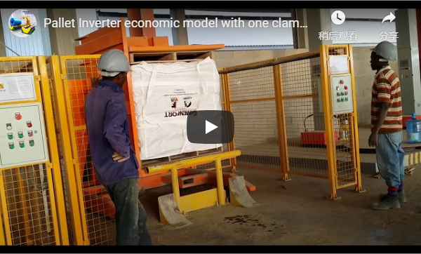
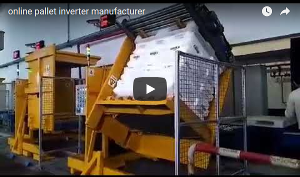
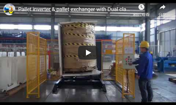
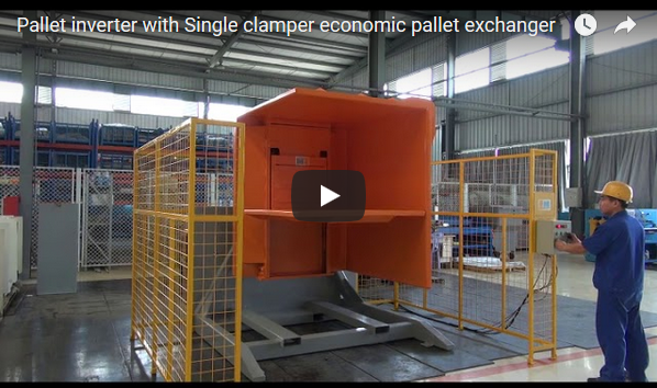
Our footage shows the clamping frame opening, swinging through the half turn and returning, with the end plates and cross beams visible. It is a general demonstration, so your load range, part size and rotation are confirmed with us per project.
Typical configuration
Figures below list functional design boundaries rather than numeric values, and are confirmed per project.
| Parameter | Typical range, confirmed per project |
|---|---|
| Load | flat part in frame |
| Clamp | hydraulic cylinders |
| Invert | frame half turn |
| Rotate | base about vertical axis |
| Mount | floor base |
| Electrical supply | 380 V three phase 50 Hz, or 220 V single phase for light machines, selected per project |
Selection checklist
| Question | Confirm per project |
|---|---|
| Load range | part size, weight, shape |
| Clamp | stroke, clearance |
| Invert | 180 degree turn, speed |
| Rotate | angle range, speed |
| Site | floor, clearance for swing |
| Electrical supply | voltage, phase and frequency on site |
Operation and safety
Place the part in the frame, close the clamp and start the turn from the control cabinet; the frame swings the part through the half turn and the base rotates it to the set orientation. Keep clear of the frame swing while the machine runs.
Routine checks cover the cylinders, the end plates and the drive, per the machine manual. Confirm the part is clamped before each turn.
Engineering FAQ
Q: What does this machine do? A: It clamps a flat part and turns it through 180 degrees, then rotates it for positioning.
Q: Why invert under power? A: A heavy flat part is dangerous to flip by hand; the frame does the half turn safely.
Q: How is the part held? A: Large end plates with hydraulic cylinders clamp the part between them.
Q: What does the rotator do? A: It turns the clamped part about the vertical axis to present the right orientation.
Q: What does it suit? A: Flat plates, panels and molds needing a half turn for the next process.
Next step
- Email us at info@fhopepack.com with your part size and weight.
- We send an inverter and rotator proposal and a layout drawing within 48 hours.
- We confirm the clamping stroke and turn angle against your part range.
Related reading
- Mechanical inverter 180 and rotator
- mold flipping table FHOPE
- Paper roll upender and titler
- FHOPE packing machinery product lines
Sources and standards
- ISO 12100:2010 Safety of machinery, general principles for design and risk assessment
- EN 415-10:2014 Safety of packaging machines, general requirements
- EN ISO 13849-1:2023 Safety of machinery, safety-related parts of control systems
FHOPE mechanical inverter 180 and rotator demonstration video. Reviewed as a general demonstration; load range, clamping stroke and rotation confirmed per project.
Last reviewed: 2026-10-11