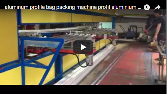
Executive summary An automatic aluminum film applicator lays a strip of protective adhesive film along the faces of each profile and cuts it between profiles. The clip, about 72 s long, shows a red and white applicator running in a profile plant, with operators at the infeed and beside the control column. Our equivalent solution runs at up to 40 m/min with a servo-driven cutter and needs one operator.
Table of Contents
- What the clip shows, in order
- Cycle time on the clip
- How the film applicator works
- Film applicator features
- Takt check
- Selection checklist for a film applicator
- Controls and safety
- Engineering FAQ
- Next step
- Related reading
- Sources
What the clip shows, in order
The applicator has a red frame with white side panels and a white control column carrying a colour screen and push buttons. Along the top runs a row of blue-green drive and pressure rollers. A yellow film head with a film roll sits in the middle, and hoses lead to it.
Behind the machine, an infeed roller rack holds a row of white aluminum profiles. The camera stays in one place for the whole clip.
- 0 to about 9 s. The applicator runs with its screen lit. Workers in yellow helmets handle profiles at the far end of the infeed rack. An operator in blue stands at the right edge of the frame, beside the machine.
- About 12 to 24 s. A worker in a yellow helmet walks up along the infeed side and stays close to the film head.
- About 27 to 33 s. The same worker stands beside the yellow film head, next to the rollers.
- About 36 to 60 s. Workers keep feeding at the far end of the rack. The operator stays at the right edge.
- About 63 to 72 s. A worker in a yellow helmet steps in front of the machine, between the control column and the film head.
Cycle time on the clip
| Step on the clip | Time window | Duration |
|---|---|---|
| Applicator running, feeding at the far end | 0 to about 9 s | about 9 s |
| Worker moves up to the film head | about 12 to 24 s | about 12 s |
| Worker beside the film head | about 27 to 33 s | about 6 s |
| Feeding continues | about 36 to 60 s | about 24 s |
| Worker in front of the machine | about 63 to 72 s | about 9 s |
The times come from frames 3 s apart. A single profile cannot be followed through the machine in these frames, so they show the work around the applicator, not a cycle per profile.
How the film applicator works
The operator feeds each profile by hand onto the infeed roller conveyor. Drive rollers then take it through the machine at a steady speed. Pressure rollers hold it in line while the film heads lay a strip of adhesive film along its top and bottom faces.
Because profiles run nose to tail, the film is continuous between them. A synchronised cutter, driven by a servo, cuts the film in the gap between two profiles, so the machine keeps running without stopping. The taped profile then leaves on the outfeed roller conveyor.
| Part | What it does |
|---|---|
| Infeed roller conveyor | Takes profiles fed by hand |
| Drive and pressure rollers | Move the profile through and hold it in line |
| Film heads | Lay adhesive film on the top and bottom faces |
| Servo cutter | Cuts the film between profiles |
| Outfeed roller conveyor | Carries taped profiles away |
| Control column with screen | Sets speed and film settings |
The tape device can be customised for profiles with irregular shapes.
Film applicator features
| Feature | Our equivalent solution |
|---|---|
| Film faces | Top and bottom sides of the profile |
| Line speed | up to 40 m/min |
| Film cutting | Synchronised cutter, servo driven |
| Infeed | Profiles fed by hand onto roller conveyors |
| Staffing | One operator online |
| Saving | 2 to 3 people against semi-automatic taping |
| Profiles | Different shapes and sizes; special tape device for irregular shapes |
The clip shows several people around the plant, including upstream handling. The one-operator figure covers the applicator itself, with profiles fed at its infeed. We confirm the profile range for each project, so we check every section before we quote.
Takt check
For an illustrative 6 m profile at 40 m/min, one pass takes 6 ÷ 40 × 60 = 9 s. With a short gap for the cutter, the applicator handles roughly 6 profiles per minute at full speed.
Hand feeding then sets the pace. One operator must place a 6 m profile every 9 to 10 s, so we size the infeed rack to keep profiles ready.
Selection checklist for a film applicator
- Profile sections and lengths.
- Faces to cover: top, bottom or both.
- Film width and type for each face.
- Profiles per hour, against up to 40 m/min.
- Space for infeed and outfeed roller conveyors.
Controls and safety
On the clip, workers stand beside the film head and in front of the machine while the rollers and film head run. Hands near the pressure rollers and the cutter are the move to design out. We guard the roller and cutter zone, so the only reach is the infeed rack.
Stop, isolate and lock out the applicator before anyone changes a film roll, adjusts a pressure roller or clears a jam at the cutter. Keep feeding at the infeed end only.
The standards that apply depend on the destination market. For CE markets, ISO 12100 sets the risk-assessment method, and EN 415-10 covers general requirements for packaging machines, which fixes guarding and the stop arrangement.
Engineering FAQ
Q: How fast does the applicator run? A: Up to 40 m/min, with infeed and outfeed roller conveyors matched to that speed.
Q: How is the film cut between profiles? A: A synchronised cutter driven by a servo cuts the film in the gap between two profiles, so the machine runs continuously.
Q: How many operators does it need? A: One operator online, which saves 2 to 3 people against semi-automatic taping.
Next step
We size an automatic aluminum film applicator in three steps:
- Submit your layout drawing with the profile sections, lengths, faces to cover and output, to info@fhopepack.com.
- Receive a proposal within 48 hours, with the applicator layout, the film set-up and the speed check.
- Book a site survey so we confirm the extrusion line, the conveyor space and the guarded roller zone.
Related reading
- Automatic profile taping machine
- Automatic aluminum profile film applicator
- Aluminum profile packing line
Sources
- Machine features: automatic profile taping machine product page
- Clip timing: frame timings taken from the clip, 3 s between frames
- Machine in action: the video on YouTube
- Standards scope: ISO 12100:2010, EN 415-10:2014
Last reviewed: 2026-10-05