Executive summary
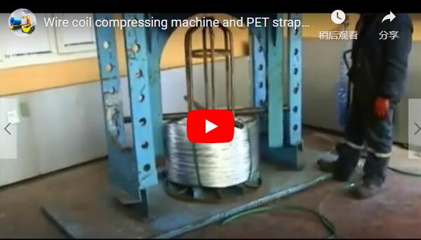
An integrated steel wire coil compressing and rack take-off machine compacts and straps heavy wire coils directly on their production carriers (Rosette racks) under 10–20 t (100–200 kN) of hydraulic force. Compacted and secured while constrained by the rack’s vertical stem, the assembly is then tilted 90° to a horizontal orientation, allowing the coil to be stripped smoothly onto external driven rollers. This eliminates coil telescoping, protects internal wire layers, and slashes stripping drive force from ~20 kN (direct vertical lift) down to 3.9–5.9 kN (horizontal draw).
Table of Contents
- Why the coil is compacted on its rack
- Integrated coil compaction and rack take-off station
- From loose coil to rack return
- Why the coil is tilted before take-off
- Worked example: stripping force for a 2 t coil
- Compacting without a rack
- Selection checklist
- Safety: EN 415-10 and ISO 12100
- Engineering FAQ
- Next step
- Related reading
- Sources
Why the coil is compacted on its rack
High-carbon and low-carbon steel wire coils are accumulated directly on tubular carriers—commonly four-post or center-stem Rosette racks—beneath the coiler or laying head. In this loose state, the coil exhibits low packing density, uneven pitch, and significant axial springback.
The center post of the rack extends fully through the coil eye (internal diameter). When the compaction platen descends, this core post serves as a rigid internal mandrel, constraining the wire loops against inward buckling or lateral dislocation.
Stripping an uncompacted, unstrapped coil from its rack before pressing creates severe processing hazards:
- Lateral misalignment: Without core support, compressive loads of 100–200 kN induce asymmetrical loop bulging, ovality, and irreversible strand cross-over.
- Telescoping: Unsupported axial compaction forces outer loops outward, jamming downstream payoff systems.
- Surface marring: Unconstrained wire layers scuff against adjacent turns under uneven pressure.
Compacting and strapping the coil while it remains anchored to the rack guarantees true cylindrical geometry, uniform density, and absolute concentricity.
Integrated coil compaction and rack take-off station
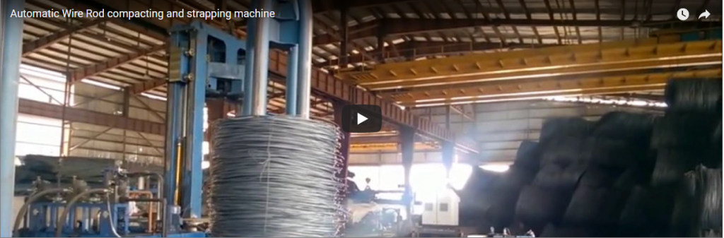
The equipment is built as a unified portal-type gantry installed directly over a heavy-duty floor conveyor line.
[Infeed Conveyor] ──> [Portal Compactor (210 bar)] ──> [90° Tilter] ──> [Horizontal Stripper] ──> [Empty Rack Return]Key Mechanical Assemblies
- Heavy Gantry Frame: Stress-relieved structural steel portal resisting 100–200 kN cyclic compaction reactions without angular deflection.
- Hydraulic Press Carriage: Dual-cylinder vertical platen driven by a 210 bar hydraulic power unit (HPU). Incorporates hardened strap pass-through guides aligned with automatic or semi-automatic strapping heads. Typical cycle time is 30–40 s per coil.
- Hydraulic Tilting Cradle (Upender): High-torque 90° hydraulic tipping chassis that secures both the compacted coil and its carrier, rotating them smoothly from vertical eye-to-sky to horizontal eye-to-horizon.
- Stripping Carriage & Roller Bed: Heavy-duty draw clamp accompanied by polyurethane-coated motorized support rollers that carry the coil body during separation from the rack stem.
- Electrical Enclosure: Integrated Rittal-grade industrial cabinet with active forced-air fan/heat exchanger and PLC automation (Siemens S7-1500 / Allen-Bradley).
From loose coil to rack return
- Rack Infeed: The loaded carrier moves via chain/roller conveyor into the portal compaction envelope and is locked into mechanical reference stops.
- Hydraulic Compaction: The upper platen descends at controlled speed, switching from fast approach to high-pressure press mode (10–20 t) to compress the wire pack to its target height.
- Circumferential / Radial Strapping: High-tensile steel or PET straps are indexed through integrated platen slots while the press holds full compressive load, neutralizing elastic springback.
- Decompression & Convey Out: The press head decompresses, retracts to home position, and the secured coil-on-rack assembly indexes into the tilting station.
- 90° Controlled Tilt: Hydraulic tipping cylinders rotate the cradle through 90°. Counterbalance valves ensure smooth deceleration without kinetic shock.
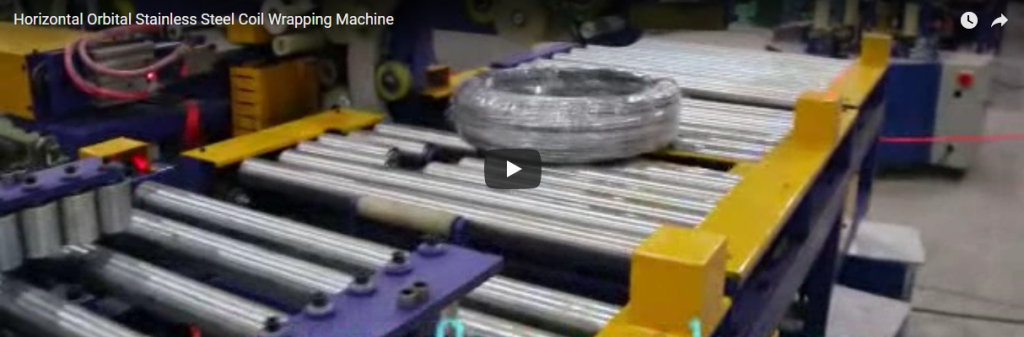
- Horizontal Take-Off (Stripping): External support rollers rise to take the external weight of the coil. An electromechanical or hydraulic stripping carriage pulls the coil off the horizontal rack post, transferring it directly to inspection or stretch wrapping.
- Rack Uprighting & Return Loop: The unloaded carrier is rotated 90° back to the vertical position and routed via an automated gravity or powered transfer loop back to the wire drawing coiler.
Why the coil is tilted before take-off
Removing a tight 2–3 ton compacted wire coil directly along a vertical axis requires overhead crane or vertical extraction masts capable of lifting the full gravitational mass (m × g), plus overcoming frictional drag between the internal wraps and the rack post. This vertical lift demands significant hall clearance, introduces overhead crane entanglement risks, and can damage rack stems under side loads.
By tilting the coil and rack 90° into a horizontal orientation:
- Gravitational Offloading: The entire static weight of the coil is transferred off the rack stem and onto heavy-duty motorized support rollers positioned underneath.
- Minimal Stripping Force: The extraction drive only needs to overcome sliding/rolling friction rather than dead gravitational weight.
- Operator & Line Safety: Heavy loads remain at low center-of-gravity transfer heights, eliminating suspended-load drop zones.
Worked example: stripping force for a 2 t coil
The following model compares vertical extraction versus horizontal draw-off for an illustrative 2,000 kg (2 t) compacted wire coil. Friction coefficients represent standard industrial dry steel-on-steel contacts (µ = 0.2–0.3).
Force Comparison Formulation
- Gravitational force:
F_g = m × g = 2,000 kg × 9.81 m/s² = 19.62 kN - Horizontal sliding stripping force:
F_strip = µ × F_normal
| Extraction Mode | Governing Equation | Normal Force (F_N) |
Applied Stripping Force |
|---|---|---|---|
| Vertical Direct Lift | F = m × g + F_friction |
19.62 kN deadweight | ≥ 19.6 kN (plus dynamic crane margins) |
| Horizontal Pull (µ = 0.2) | F = 0.2 × (m × g) |
19.62 kN (on carrier stem) | ≈ 3.9 kN |
| Horizontal Pull (µ = 0.3) | F = 0.3 × (m × g) |
19.62 kN (worst-case contact) | ≈ 5.9 kN |
| Roller-Supported Take-off | F = µ_rolling × (m × g) |
19.62 kN (transferred to rollers) | < 1.0 kN (µ_r ≤ 0.05) |
Engineering Assessment: In the worst-case horizontal condition where the rack stem bears the entire normal force, stripping requires only 3.9–5.9 kN of tractive effort—a 70% to 80% reduction in drive rating compared to vertical hoisting. Once external polyurethane support rollers contact and lift the pack outer diameter, rolling resistance drops below µ_r = 0.05, allowing smooth, wear-free coil transfer.
Compacting without a rack
For wire facilities requiring off-line carrier return before strapping, two engineered alternative configurations are available:
- Expanding Internal Mandrel (Core Guide): A precision, heavy-wall guide cylinder lowers from the upper gantry directly into the coil eye before hydraulic ram stroke initiation. It maintains bore roundness throughout the 210 bar press cycle and retracts vertically before radial strapping.
- External Segmented Containment Basket: Multi-segment pneumatic or hydraulic containment jaws encircle the coil outer diameter. These segments close during pressing to restrain radial wire expansion, retracting outward once strapping heads complete strap tensioning.
Selection checklist
To receive an exact equipment footprint and load specification, provide the following line parameters:
- Coil Geometry: Maximum and minimum Outer Diameter (OD), Inner Diameter (ID), loose height, and total mass (kg).
- Rack Profile: Carrier type (Rosette, four-pillar, or hollow pipe), post wall thickness, footprint drawing, and centering tolerances.
- Packaging Requirements: Target compressed height, strap material (High-Tensile Steel vs. Polyester PET), and strap layout (2, 3, or 4 radial ties).
- Downstream Routing: Target height of discharge conveyor, integration with orbital stretch wrappers, or crane hook pickup.
- Return Logistics: Powered roller circuit, cross-bay transfer car, or AGV interface for empty carriers.
- Civil & Foundation Constraints: Floor load-bearing capacity (kN/m²), pit allowances, and overhead crane clearance limits.
Safety: EN 415-10 and ISO 12100
All stations are engineered to comply with EN 415-10 (Safety of packaging machines: Compacting machines) and evaluated via risk assessment protocols under ISO 12100:2010.
- Perimeter Guarding & Interlocks: Cat 4 / PL e dual-channel interlocked perimeter fencing around the gantry and tilting radius.
- Hydraulic Gravity Fall Protection: Dual-channel pilot-operated check valves and mechanical rod locks prevent hydraulic platen descent during maintenance or manual strap insertion.
- Safe Motion Zones: 90° tilting cradle includes optical safety light curtains and acoustic-optical beacons active during upending cycles.
- LOTO Compliance: Dedicated lockable electrical isolators and residual pressure dump valves on the main hydraulic manifold.
Engineering FAQ
Q: Why not strip the wire coil off the rack prior to compaction? A: The rack’s structural core post acts as an internal mandrel. Compacting an unconstrained coil causes severe core distortion, wire cross-overs, and lateral buckling under 100–200 kN axial forces.
Q: What hydraulic pressure and force ratings are standard? A: Standard systems utilize a 210 bar hydraulic power unit delivering 10–20 t (100–200 kN) of compressive load, tailored to specific wire alloy stiffness and coil density targets.
Q: Are deep foundation pits required for installation? A: Most models are surface-mounted directly onto a reinforced industrial concrete floor slab (typically 250–300 mm, C30/37). Pit installations are only required when conveyor top-of-roller height must align flush with factory floor grade.
Q: How is factory acceptance testing (FAT) conducted prior to delivery? A: Every machine undergoes complete mechanical, electrical, and hydraulic dry testing in our workshop under automated PLC sequencing. Customer-supplied racks and dummy coils are used to verify pressing force, 90° tilting deceleration, and stripper tractive force.
Q: What machine directives govern CE documentation? A: Full compliance with the European Machinery Directive 2006/42/EC, EN 415-10 for compactors, EN ISO 13849-1 for control safety circuits, and ISO 12100 risk assessments.
Next step
- Submit Line Specifications: Email your coil data sheet (OD/ID/Weight) and carrier drawings to info@fhopepack.com.
- Engineering Layout Review: Our packaging automation team delivers a certified 2D General Arrangement (GA) drawing and 3D layout showing compaction, tilting, and carrier return loops.
- Turnkey Proposal: Receive a formal technical and commercial quotation within 24 hours.
Related reading
- Wire rod compactor (product)
- Automatic steel wire compacting and spool take-off
- Automatic steel wire rod coil compressing with strapping machine
- Steel wire coil compressing machine with moving clamp
Sources
- FHOPE Heavy Industry Packaging Systems Design Manual (Wire & Rod Compaction Series)
- FHOPE Technical Application Notes: Hydraulic Compaction, 90° Upending, and Carrier Return Loops
- Mechanical Design Standards: EN 415-10 (Compacting and Strapping Safety Requirements)
- Risk Assessment and Hazard Control: ISO 12100:2010
- Fluid Power Engineering: ISO 4413:2010 (Hydraulic fluid power general rules and safety)
Last reviewed: 2026-10-18