DIE Mould Upender and Tilter: Engineering Analysis for Enhanced Safety and Efficiency in Heavy Tooling Handling
1. Introduction: Addressing Critical Challenges in Die and Mould Manipulation
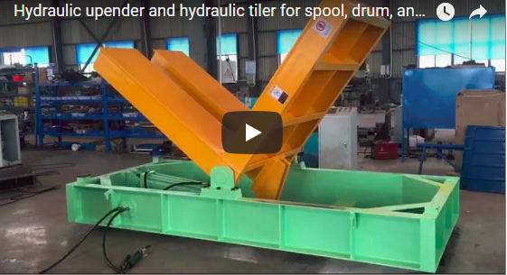
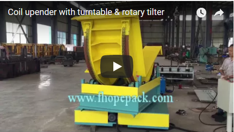
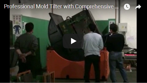
The manipulation of large-tonnage dies and moulds is a fundamental requirement in numerous heavy industrial sectors, including automotive stamping, aerospace component manufacturing, and plastics injection molding. However, conventional handling methods, often relying on overhead cranes and complex rigging, introduce substantial risks. These include potential load instability leading to catastrophic tooling damage, significant safety hazards for personnel (crush, pinch points), and inefficiencies that impede rapid tool changes (a core tenet of methodologies like SMED - Single-Minute Exchange of Die). Inefficient and unsafe handling directly impacts productivity metrics, increases operational costs, and poses ergonomic threats. The DIE Mould Upender and Tilter is an engineered material handling solution specifically designed to mitigate these challenges. This equipment provides controlled, precise, and safe 90° (or greater) rotation of heavy tooling, facilitating critical maintenance, inspection, cleaning, and repositioning operations while optimizing workflow and adhering to stringent industrial safety standards (e.g., ISO 12100, OSHA).
2. Engineering Design and Structural Integrity
The performance and safety of the DIE Mould Upender and Tilter are rooted in robust engineering design, material selection, and integrated safety systems.
2.1. Structural Framework and Load Platform
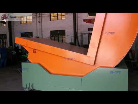
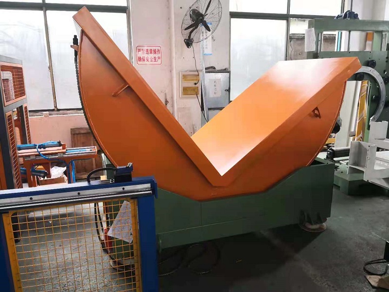
The core structure is typically fabricated from high-strength structural steel (e.g., S355JR or equivalent), designed and verified using Finite Element Analysis (FEA) to withstand maximum rated loads plus appropriate safety factors under dynamic tilting conditions. The standard load platform (e.g., 2000 mm x 2000 mm) provides a stable base, often customizable in dimension and surface treatment (e.g., non-slip coatings, T-slots, custom locators) to securely accommodate diverse die/mould base geometries. Weldments adhere to relevant standards (e.g., AWS D1.1) ensuring structural integrity.
2.2. Drive System Mechanics
The tilting motion is commonly actuated via an electro-hydraulic system. Key components include:
- Hydraulic Cylinders: Heavy-duty, industrial-grade cylinders, often synchronized for smooth, level tilting, equipped with pilot-operated check valves or load-holding valves to prevent descent in case of hydraulic pressure loss.
- Hydraulic Power Unit (HPU): Comprising an electric motor, hydraulic pump, reservoir, filtration, and control valving, sized for the required flow rate and pressure to achieve desired tilting speeds under full load.
- Alternative Drives: For specific applications, electro-mechanical drives utilizing high-capacity screw jacks or roller chain systems may be employed, offering different operational characteristics (e.g., precise positioning, no hydraulic fluid).
2.3. Control System and Safety Integration
Modern units utilize Programmable Logic Controllers (PLCs – e.g., Siemens S7 series, Allen-Bradley ControlLogix) for reliable process control and safety function integration.
- Operator Interface: A Human-Machine Interface (HMI) touch screen typically provides intuitive control over start/stop, tilting speed adjustment, angle selection, and displays system status, alarms, and diagnostic information. Remote pendant control is often an option for operator flexibility.
- Safety Features: Essential safety components are integrated according to risk assessments based on standards like ISO 13849-1 (Safety of machinery – Safety-related parts of control systems). These include:
- Emergency stop circuits (E-stops) readily accessible.
- Limit switches to define the end-of-travel for the tilting range.
- Hydraulic load-holding valves.
- Potential integration of safety interlocks with physical guarding or light curtains to prevent access during operation.
- Overload protection mechanisms within the hydraulic or electrical system.
3. Key Technical Specifications (Typical Ranges)
- Load Capacity: 10,000 kg (10 tons) / 15,000 kg (15 tons) - Higher and custom capacities available based on application analysis.
- Standard Platform Size (L x W): 2000 mm x 2000 mm - Fully customizable.
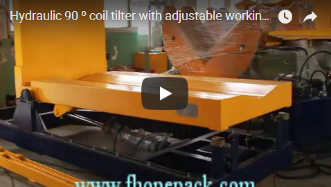
- Tilting Range: Standard 0° to 90° (Horizontal to Vertical). Extended ranges (e.g., 0-180°) available.
- Tilting Speed: Adjustable, typically 1-3 degrees/second (dependent on HPU sizing and load).
- Drive System: Electro-hydraulic (standard); Electro-mechanical (optional).
- Main Motor Power: Dependent on capacity and speed (e.g., 5.5 kW - 15 kW).
- Power Supply: 380V/400V/480V, 50/60Hz, 3-Phase - Specify required standard.
- Control Voltage: 24V DC (typical for control circuits).
- Control System: PLC with HMI Touch Screen.
- Paint Finish: Industrial enamel or powder coating (custom RAL colors available).
- Safety Compliance: Designed to meet CE Machinery Directive, OSHA guidelines, relevant ISO/ANSI standards.
4. Primary Industrial Application Sectors
The utility of the DIE Mould Upender and Tilter spans industries requiring safe handling of heavy tooling:
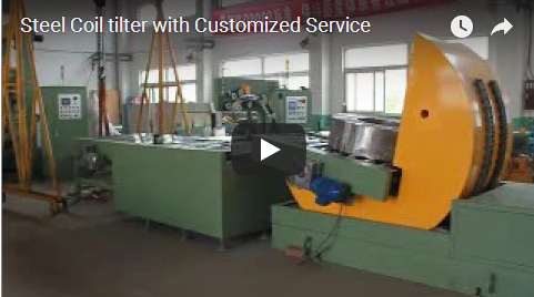
- Automotive Stamping: Handling large body panel, chassis, and powertrain dies for maintenance, cleaning, and transport to/from presses. Critical for SMED initiatives.
- Plastics Injection & Blow Molding: Rotating heavy molds for maintenance, repair, cleaning, and changeouts on molding machines.
- Die Casting: Manipulating large, multi-part dies used in high-pressure aluminum, zinc, or magnesium casting.
- Aerospace Manufacturing: Positioning complex molds and fixtures for composite layup, bonding, or machining of large structural components.
- Heavy Equipment Manufacturing: Tilting large weldments, fixtures, and tooling components during fabrication processes.
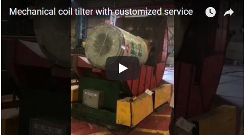
- Tool and Die Shops: Providing safe and efficient handling during the manufacture, repair, and maintenance of customer tooling.
5. Quantifiable Engineering and Operational Advantages
Implementing a dedicated DIE Mould Upender and Tilter delivers measurable improvements:
- Significantly Enhanced Safety: Drastically reduces risks associated with suspended loads, manual prying, and awkward postures inherent in crane/rigging methods. Addresses OSHA focus areas for preventing MSDs and severe injuries.
- Improved Operational Efficiency: Reduces die/mould rotation time by potentially 50-75% or more compared to traditional rigging, directly shortening changeover times and increasing machine uptime.
- Precision and Control: Provides smooth, controlled motion with precise angular positioning, preventing shock loads and allowing for careful inspection or work.
- Asset Protection: Minimizes the risk of accidental damage to expensive dies and molds caused by impacts, drops, or improper handling. Estimated reduction in tooling damage incidents can be substantial.
- Optimized Labor Utilization: Enables a single trained operator to perform the tilting operation safely, freeing up personnel previously required for complex rigging and spotting.
- Floor Space Optimization: Can lead to a more organized workflow and potentially reduce the large clear area required for crane-based maneuvers.
- High Reliability: Engineered with robust industrial components for durability and long service life in demanding production environments. Requires standard preventative maintenance.
6. User Perspective: Operational Transformation
"Implementing the 15-ton DIE Mould Upender has fundamentally changed our toolroom operations. Changeover times involving mold rotation have decreased by a measured average of 40%. Beyond the numbers, the biggest impact is on safety. Our team feels much more secure handling these heavy molds, and we've eliminated near-miss incidents related to the old crane and chain method. The HMI is straightforward, and the control is incredibly smooth. It’s proven to be a non-negotiable piece of equipment for safety and efficiency." - Lead Tooling Engineer, Automotive Tier 1 Supplier.
7. Performance Comparison: Engineered Tilter vs. Traditional Methods
| Parameter | Traditional Crane & Manual Rigging | Dedicated DIE Mould Upender and Tilter |
|---|---|---|
| Safety | High Risk (load swing, rigging failure, pinch points, ergonomics) | Very Low Risk (controlled motion, interlocks, load holding) |
| Cycle Time | Slow (setup, rigging, multiple lifts, slow maneuvering) | Fast (quick setup, single controlled motion) |
| Positional Accuracy | Low to Moderate (operator dependent, load sway) | High (precise angle control, repeatable) |
| Personnel Req. | 2-3+ (Crane Op, Rigger, Spotter) | 1 Operator |
| Tooling Damage Risk | Moderate to High (impacts, drops, instability) | Very Low (secure platform, controlled tilt) |
| Ergonomic Load | High (manual pushing/pulling, awkward postures) | Minimal (push-button/HMI operation) |
| Floor Space Req. | Large clear area needed for maneuvering | Defined equipment footprint |
| Training Req. | Certified Crane Op, Certified Rigger | Specific Equipment Operator Training |
8. Implementation: Installation, Commissioning & Lifecycle Support
Successful integration requires a comprehensive approach:
- Application Review & Customization: Detailed analysis of load characteristics, facility layout, and workflow to ensure proper sizing and feature selection.
- Foundation Requirements: Assessment and preparation of adequate concrete foundation to support the equipment weight and dynamic loads.
- Installation & Commissioning: Professional setup, connection of utilities (electrical, potentially compressed air), calibration, load testing, and safety function verification by qualified technicians.
- Operator & Maintenance Training: Hands-on training covering safe operation procedures, HMI navigation, daily checks, fault finding, and preventative maintenance schedules.
- Documentation: Provision of comprehensive manuals (Operation, Maintenance, Electrical/Hydraulic Schematics, Parts List).
- After-Sales Service: Availability of technical support, spare parts inventory, and optional service agreements for ongoing maintenance and support.
9. Conclusion: A Strategic Investment in Manufacturing Performance and Safety
The DIE Mould Upender and Tilter transcends being merely a piece of handling equipment; it is a strategic engineering solution addressing core challenges in heavy industrial manufacturing. By leveraging sound mechanical design, reliable drive systems, sophisticated controls, and integrated safety features aligned with global standards, it delivers quantifiable improvements in operational efficiency, significantly enhances personnel safety, and protects valuable tooling assets. For facilities managing large dies and molds, investing in this technology aligns with lean manufacturing principles, reduces operational risk, and contributes directly to a safer, more productive, and competitive manufacturing environment.
10. Take the Next Step
To explore how a DIE Mould Upender and Tilter can be tailored to your specific heavy load handling requirements, contact our engineering team. We can provide detailed technical consultations, customized proposals, and help you quantify the safety and efficiency benefits for your operation.