fhopepack-logo

+86 13951501635

24/7 Customer Support

Understanding the pricing of industrial coil upenders requires examining it from two distinct viewpoints: direct from the manufacturer and through the broader online marketplace. Each offers different insights into cost structures and purchasing processes.

I. Manufacturer Pricing Perspective: The "Request Quote" Model

Manufacturers of industrial coil upenders, particularly those producing heavy-duty, specialized, or highly customized units, typically do not publish fixed price lists. Instead, a "Request Quote" or "Build to Order" approach is prevalent. This methodology is driven by several key factors in coil upender price:

  • Extensive Customization and Configuration:

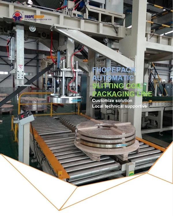
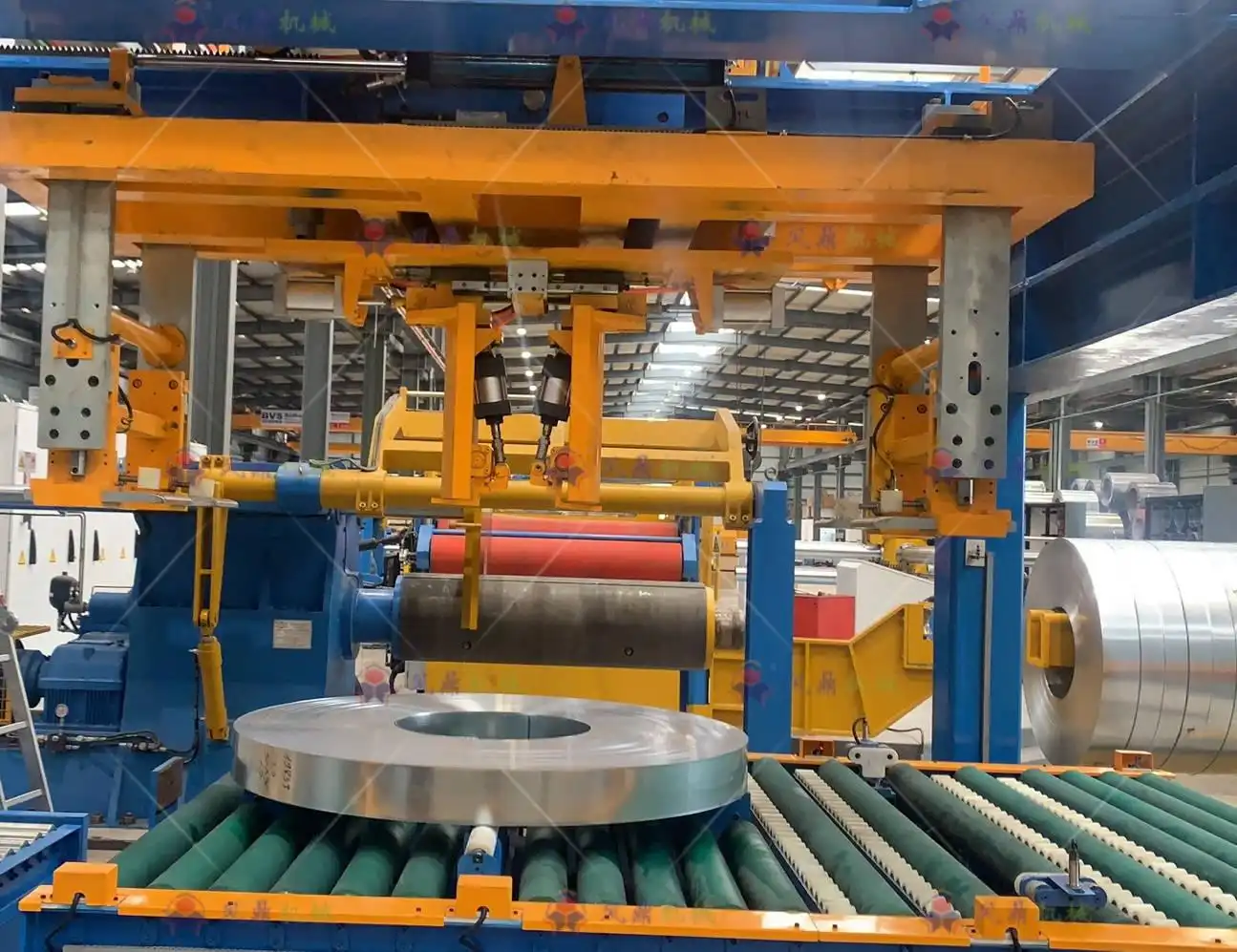
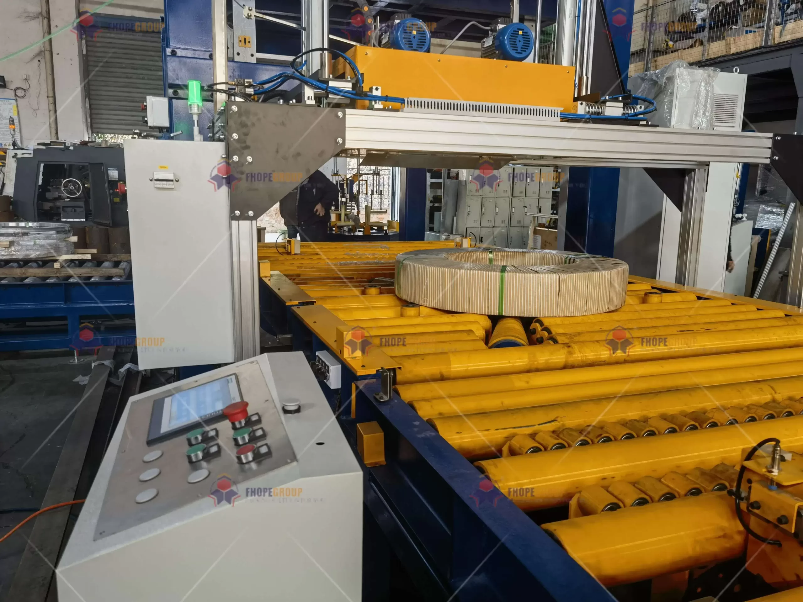
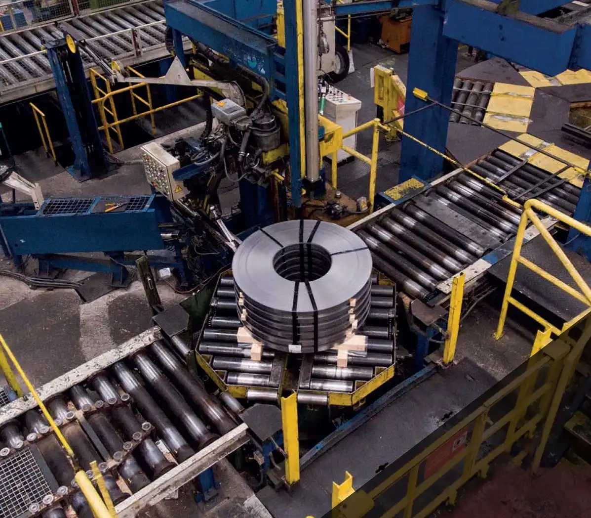
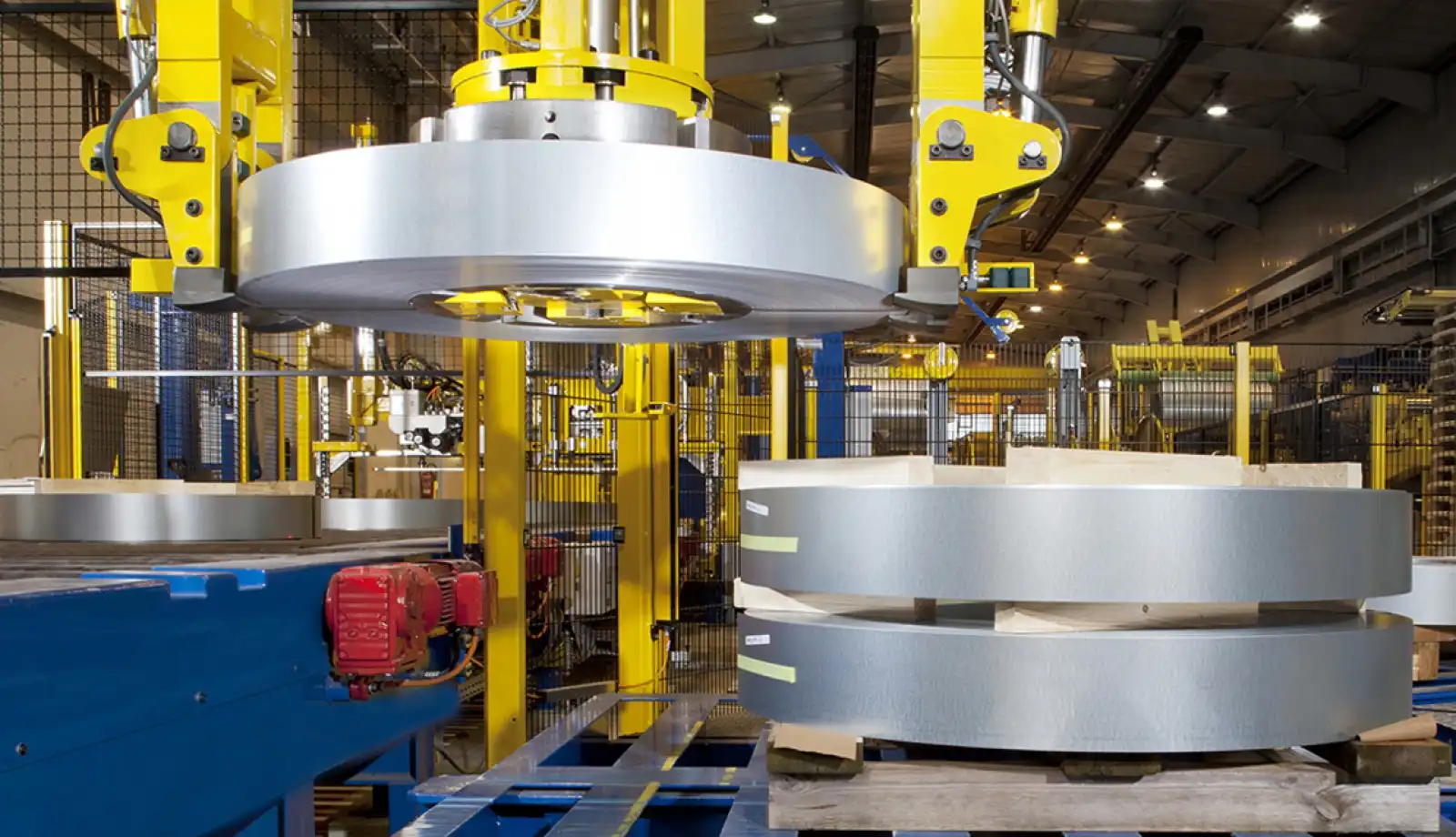
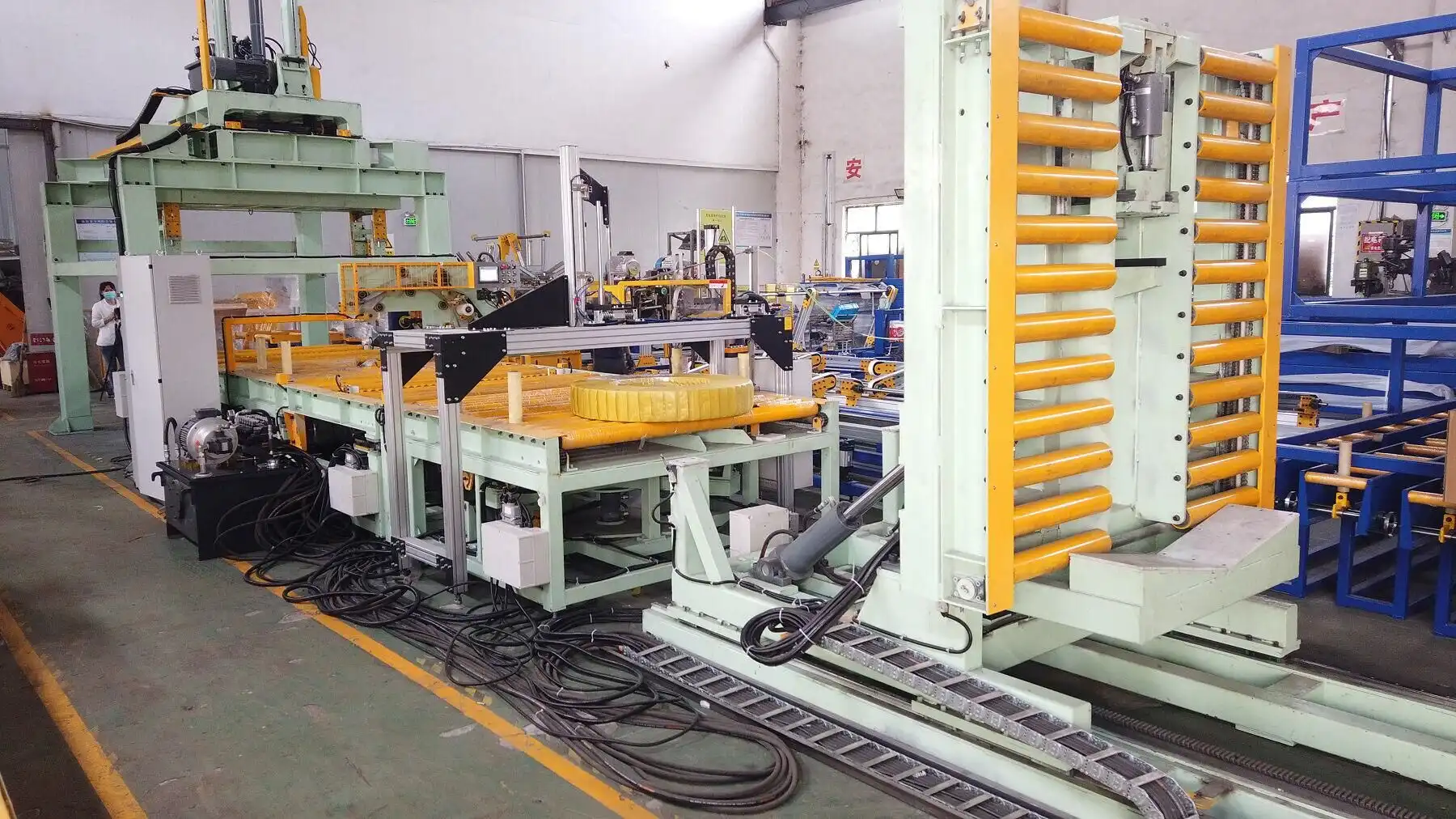
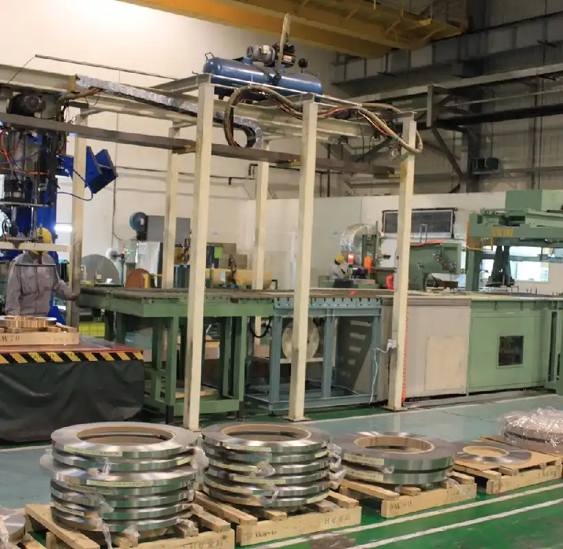
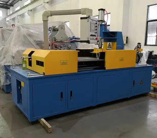
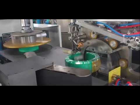
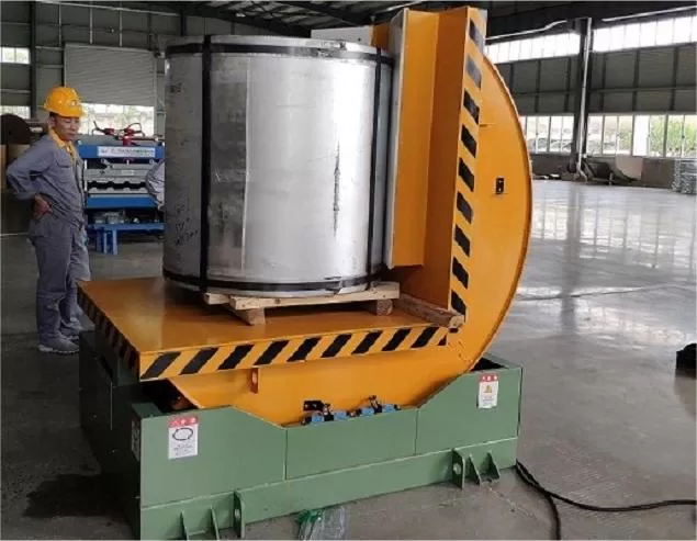
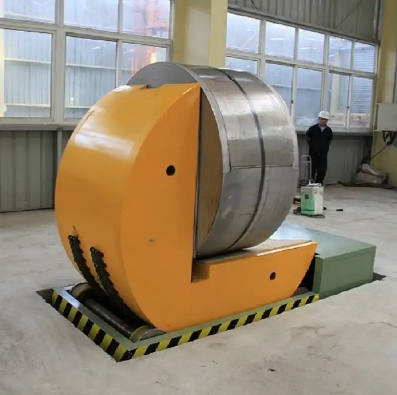
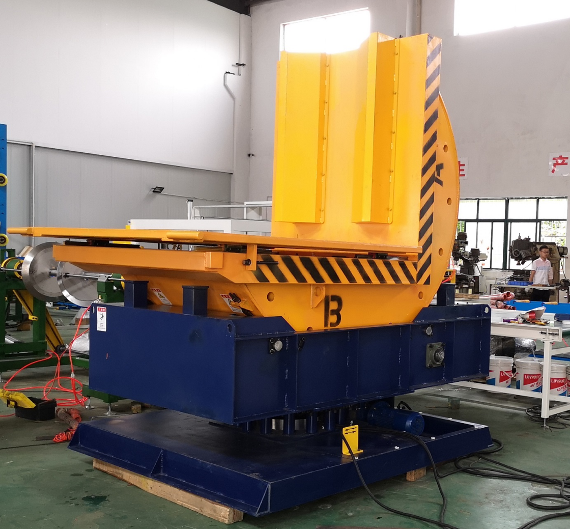
    • Coil upenders can vary significantly in critical specifications such as capacity (ranging from a few tons to 70 tons or more), table size, drive mechanism (electric mechanical or hydraulic), control systems, and integrated safety features.
    • A substantial number of units are engineered to precise customer requirements, making a standard price list impractical. For instance, MetalPress Machinery offers its MDR series with capacities from 5 to 70 tonnes and various optional features like rotating bases or forklift bases, all of which directly influence the final price.
  • Consultative Sales Process:

    • The acquisition of such machinery often necessitates detailed discussions between the buyer and the manufacturer (or their authorized distributor). This ensures the equipment precisely aligns with the intended application.
    • This consultative approach helps define the exact specifications needed, which subsequently informs the price quotation.
  • Value-Based Pricing Strategy:

    • Manufacturers may price their equipment based on the tangible value it delivers to the customer. This includes benefits like increased productivity, enhanced operational safety, and reduced maintenance requirements (e.g., all-electric designs that eliminate hydraulic leak concerns).
    • This value proposition can be more effectively articulated and justified through direct interaction rather than a static price tag.
  • Competitive B2B Strategy:

    • In a business-to-business (B2B) environment, manufacturers often prefer to discuss pricing directly. This allows them to better understand the competitive landscape for a specific sale and potentially negotiate terms.
    • Companies like MetalPress Machinery, while promoting their upenders as "competitively priced" and "loaded with features and value," require potential buyers to "request more info" or "GET QUOTE." Similarly, distributors of brands like SXKH for larger or specialized mechanical or hydraulic flippers (which share technological similarities with upenders) also frequently employ a "Request Quote" system.

      II. Market View Pricing: Online Marketplaces & General Listings

The broader market, particularly online B2B platforms such as Alibaba, provides more direct price visibility. This is primarily for more standardized or smaller-capacity coil upenders, often originating from Asian manufacturers. These listings offer a general benchmark for what basic or less customized units might cost.

Here's what the market view indicates:

  • Wide Price Spectrum: Prices can span significantly, from approximately $1,500 to $14,885 USD, and potentially higher, contingent on the specifications.

  • Entry-Level/Basic Units:

    • A 0-90 degree hydraulic upender for flipping metal (suitable for some coil applications) can be found for around $1,500.
    • Vertical-horizontal turnover machine coil upenders are listed in the vicinity of $2,500.
  • Mid-Range Units:

    • 5-ton steel coil turnover machines (90-degree flip) are priced near $2,750.
    • 180-degree mold and coil upenders/flippers can range from $5,400 to $6,000.
    • 90-degree industrial flip machines or steel coil turnover machines (2,000-30,000kg capacity) are listed between $5,800 and $6,000.
  • Branded/Higher Capacity Units (on these platforms):

    • WALTER 90-degree steel/aluminum coil tippers and upenders (3T-30T capacity) are listed in ranges like $3,355 - $8,855.
    • "Chinese Top Brand WALTER 3T-30T Turn Over Steel Coil" machines show prices from $5,650 to $14,885.
  • Customized Units (on these platforms):

    • Even on platforms like Alibaba, some listings mention "Customized" upenders. For example, a 50-ton 90-degree large die/mold flipper (which could potentially handle coils) is listed for around $3,000, though this price might represent a base figure for further customization.

      III. Summary of Price Analytics

  • Manufacturer Direct:

    • Expect a consultative purchasing process with pricing provided via quotation. This is especially true for heavy-duty, high-capacity, or extensively customized coil upenders.
    • Prices will reflect the specific engineering involved, features included, and the level of support offered. These solutions are generally positioned as higher-value and, potentially, higher-cost options.
  • Market (Online Platforms):

    • Offers greater price transparency for a spectrum of generally smaller to medium-capacity coil upenders.
    • Prices typically range from a couple of thousand dollars to the mid-teen thousands. This market segment is often more price-competitive for standard functionalities.

Conclusion:

To obtain an accurate coil upender price for a coil upender that meets specific industrial requirements, direct engagement with manufacturers or their authorized distributors is usually necessary. This allows for a detailed definition of needs and a formal quotation. Online marketplaces can serve as a valuable resource for a baseline understanding of pricing for more generic or lower-capacity options.

Stop Guessing, Start Saving: Calculate Coil Packing Costs Instantly (USD)

In the fast-paced world of manufacturing and logistics, efficiency and cost control are paramount. When it comes to packaging coils – whether steel, wire, cable, or pipes – accurately estimating material usage and cost can be a tedious, time-consuming, and often inaccurate process. Manual calculations are prone to errors, leading to material waste, budget overruns, and lost productivity.

What if you could eliminate the guesswork? What if you had a tool that instantly calculated the required packing material area, weight, and estimated cost for eye-through coil wrapping?

Introducing the Coil Packing Material & Cost Calculator by Fhopepack – your new essential tool for precise packaging planning.

Try the FREE Coil Packing Material & Cost Calculator Now! <<

Why Accurate Packing Calculation Matters

Underestimating packing material leads to unprotected goods and potential damage during transit. Overestimating means wasted material and inflated costs that eat into your profit margins. Getting it right is crucial for:

  • Budgeting: Accurately forecast packaging expenses.
  • Procurement: Order the right amount of stretch film, kraft paper, or woven fabric.
  • Efficiency: Reduce time spent on manual calculations.
  • Sustainability: Minimize material waste.

Features of the Fhopepack Coil Packing Calculator

Our free online calculator is designed with industry needs in mind, offering a simple yet powerful solution:

  • Versatile Product Types: Calculate for various coil types, including Steel, Wire, Hose, Pipe, Copper, Aluminum, Tires, Cables, Bearings, and more.
  • Multiple Material Options: Choose from standard packing materials like Stretch Film (20g/m²), Kraft Paper (185g/m²), and Woven Fabric (115g/m²), complete with estimated USD prices per kg.
  • Custom Material Input: Have specific material requirements? Select "Custom" and input your material's weight (g/m²) and price ($/kg) for tailored calculations.
  • Precise Dimension Inputs: Enter your coil's Outside Diameter (OD), Inside Diameter (ID), and Width/Thickness (T) in millimeters.

  • Overlap Consideration: Factor in the crucial overlap rate (%) for realistic material usage estimates in eye-through wrapping.
  • Instant Results: Get immediate calculations for:
    • Required Material Area (m²)
    • Estimated Material Weight (kg)
    • Estimated Cost per Unit ($ USD)
  • Dynamic Visualization: See a simplified top-down animation of the eye-through wrapping process, helping visualize how the coil gets covered.
  • Price Disclaimer: We provide realistic price estimates but include a clear note that actual costs vary. For precise quotes, contact us directly.

How to Use the Calculator (It's Easy!)

  1. Select Product Type: Choose the type of coil you are wrapping.
  2. Select Packing Material: Pick a standard material or choose "Custom".
  3. (If Custom): Enter your material's weight and price per kg.
  4. Enter Dimensions: Input the OD, ID, and T (Width/Thickness) in mm.
  5. Enter Overlap Rate: Input the desired overlap percentage (e.g., 50).
  6. Click Calculate: Instantly view the results!

Optimize Your Coil Packaging Today

Stop relying on rough estimates or complex spreadsheets. The Fhopepack Coil Packing Material & Cost Calculator provides the speed and accuracy you need to streamline your packaging operations, control costs, and reduce waste. It's an invaluable tool for procurement managers, logistics coordinators, production planners, and anyone involved in industrial coil packaging.

Ready to take control of your packaging costs?

Try the FREE Coil Packing Material & Cost Calculator Now! <<

Don't forget to check out our range of high-quality Coil Wrapping Machines designed for efficiency and reliability. For specific pricing on materials or machinery, please Contact Us.

In today’s fast-paced manufacturing and logistics environments, automation plays a crucial role in improving overall operational efficiency and reducing labor costs. One of the most impactful areas for automation is the packaging stage, specifically in strapping systems that ensure products are securely bundled for shipping or storage. When designing or selecting a modern strapping machine, several technical parameters and considerations come into play, such as the pneumatic design, the required air pressure and flow (CFM usage), the communication between different PLCs (Programmable Logic Controllers), and adherence to various certification standards. This article offers a detailed analysis of the technology behind strapping machines, examining each component and parameter to provide insights that will help engineers, operations managers, and decision-makers make well-informed choices.

board strapping machine


1. Understanding the Pneumatic Design

Strapping machines, especially those developed for large-scale industrial applications, frequently rely on pneumatic systems for reliable, repeatable motion. The pneumatic elements control actions such as tensioning, sealing, cutting, and even positioning packages before and after strapping. These actions must be both accurate and consistent to ensure a secure wrap without damaging the product.

Key Pneumatic Inputs:

  • Pressure Range: Approximately 0.4 to 0.6 Mbar (sometimes described in bar or psi equivalents)

  • Air Consumption: Around 100 mL per minute

At first glance, these numbers may appear small, but the actual volumetric flow or CFM (cubic feet per minute) consumption can be much higher depending on the frequency of strapping and the system’s cylinder sizes. Each pneumatic stroke—whether it is driving the strap feed, activating tension, or sealing—draws upon the compressed air supply. If your production line is continuous and requires frequent strapping (e.g., every few seconds), the cumulative CFM requirement can become substantial.

Why Pneumatics?

  • Reliability and simplicity: Pneumatic components are typically straightforward to maintain, and spare parts are widely available.

  • Clean operation: Compressed air is generally considered “clean” compared to hydraulic fluids, which can leak or contaminate the workspace.

  • Quick response times: Pneumatic cylinders can provide rapid actuation critical for high-throughput packaging lines.

Before integrating a pneumatic strapping machine into your production line, it is vital to perform an in-depth analysis of your compressed air capacity. This includes understanding the available air pressure from the facility’s air system, the size of the air tank(s), and the presence of any additional pneumatic equipment that might create pressure fluctuations. Installing a well-sized air reservoir tank and filters or regulators can help mitigate sudden pressure drops and maintain the stability required for precise strapping operations.


2. Detailed Look at CFM Usage

While a nominal figure of 100 mL/min might be stated as the consumption rate, the actual operational CFM can vary significantly based on duty cycle. Consider the following factors:

  1. Cycle Time: If your system performs strapping every 10 seconds, the total air usage per minute will be much higher than if strapping occurs once a minute.

  2. Cylinder Dimensions: Larger cylinders require greater volume per stroke. The tensioning cylinder, sealing cylinder, and additional pneumatic actuators (for clamp blocks or conveyors) all contribute to total consumption.

  3. Operating Pressure: Operating near the upper range of 0.6 Mbar will generally consume more air per actuation than operating at 0.4 Mbar, though this must be balanced with ensuring sufficient power for tensioning and sealing.

Companies often find it beneficial to track real-time air consumption to prevent unplanned downtime. A well-structured preventative maintenance plan, including regular checks of air hoses, seals, and regulators, can minimize air leaks. Even minor leaks that go unnoticed can significantly impact the compressor’s duty cycle and energy cost over time.

autoamtic pet strapping machine


3. PLC Communication: Two Approaches for Integration

One of the critical steps in automating a strapping station is ensuring seamless communication between the strapping machine’s PLC and the conveyor or other upstream/downstream equipment controllers. This coordination controls when packages enter the strapping zone, when the strapping cycle commences, and when the packaged product is discharged. Two primary communication methods are commonly employed:

  1. Solution 1: A Self-Contained Conveyor System Provided by the Strapping Machine Supplier
    In this scenario, the strapping machine supplier provides the entire conveyor line. The built-in sensors and drives allow the machine to detect when a package is present and automatically position it for strapping without requiring extensive external PLC integration. Typically, only two sensors are necessary—one at the end of the inbound conveyor and one at the start of the receiving conveyor—to detect package flow. Since the strapping machine controls both conveyors, the entire process is streamlined with minimal signals exchanged between external systems.

  2. Solution 2: Separate Conveyor Owned by the Customer
    When the customer already has a conveyor system in place or prefers a specific conveyor design, integration relies on exchanging I/O signals (often digital inputs and outputs) between the strapping machine’s PLC and the customer’s PLC. A common sequence might look like this:

    • The external PLC sends an “A” signal to the strapping machine when a package is in the correct position.

    • Upon receiving the “A” signal, the strapping machine’s blocking mechanism engages, securing the package in place. The machine then performs the strapping cycle.

    • Once strapping is complete, the strapping machine sends a “B” signal to the external PLC to move the package away.

    • The external PLC advances the package off the strapping station and eventually returns the “A” signal when the next package is in position.

This signal-based interplay can be repeated for multiple strapping operations if the product needs multiple straps. With well-defined logic and carefully timed signals, the entire process can be automated to a high degree, ensuring minimal downtime and maximizing throughput.


4. Automation Level: Balancing Manual and Automatic Operations

A common question for prospective buyers is whether each strap requires manual intervention or if the entire process can be fully automated. Modern strapping machines are capable of highly automated operations, minimizing manual involvement. The operator’s main responsibilities typically include:

  • Reloading Corner Protectors: For example, if four straps are applied per package, corner protector cartridges might need reloading every 25 packages, which can be roughly once per hour. In more customized solutions, it can extend to 1.5–2 hours per reload, depending on the machine’s capacity and the size of protector holders.

  • Reloading PET Straps or Other Strapping Materials: The strapping reel might hold enough material for 120 packages before requiring a refill.

Aside from these occasional tasks, the strapping process itself does not require operators to stand at the machine and manually trigger each cycle. The entire sequence—package infeed, alignment, strap tensioning, sealing, cutting, and outfeed—can be programmed and automated. This high level of automation reduces labor costs, enhances consistency, and frees operators to focus on other tasks in the packaging area.

wooden strapping machine


5. Certification Considerations: CE vs. UL

When deploying equipment globally, certification standards become a top priority. European markets typically mandate CE certification, confirming that the machine meets health, safety, and environmental protection requirements within the European Economic Area. In North America, UL certification is often the benchmark for ensuring equipment meets fire safety and electrical standards.

UL Certification Challenges:

  • High Cost and Long Process: Obtaining UL certification can be expensive and time-consuming for manufacturers, particularly when dealing with custom or specialized machinery.

  • Practical Approach: Many suppliers build their machines according to UL standards but do not directly apply for UL certification in the manufacturing country. Instead, they ship machines to the United States or Canada, where local testing labs finalize the certification process for the end customer. This approach can be more cost-effective, especially for businesses that do not plan high-volume machine exports.

For end users in North America, it is still advisable to work with suppliers who understand UL guidelines and can deliver machines that easily pass UL inspections. By ensuring compliance during the design phase, the overall time to achieve final UL labeling on-site can be drastically reduced.


6. Conclusion: Toward a More Efficient and Global-Ready Strapping Line

Designing and integrating a pneumatic strapping machine involves careful consideration of air supply requirements, communication with external or internal PLCs, the desired automation level, and potential certification pathways. By focusing on these technical elements from the outset, companies can avoid common pitfalls such as insufficient air pressure, misaligned signal timing, or issues with regulatory compliance.

Moreover, as part of a broader Industry 4.0 or smart factory initiative, strapping machines can be integrated into larger MES (Manufacturing Execution Systems) or ERP (Enterprise Resource Planning) platforms. This allows for real-time tracking of strapping frequency, material usage, and machine health, which in turn enables predictive maintenance and optimized production scheduling.

In summary, a well-chosen strapping solution isn’t just about strapping products securely—it’s about creating a seamless, efficient, and data-driven operation. By taking into account pneumatic design details, PLC communication nuances, automation capabilities, and global certification standards, businesses can implement a system that supports current needs and remains adaptable for future growth.

For those looking to stay at the forefront of industrial packaging technology, selecting a robust pneumatic strapping machine that aligns with UL standards (or CE requirements in Europe) is a key strategic move. Whether fully automated or semi-automated, these solutions can significantly reduce labor demands while improving packaging consistency and throughput. If you are in the process of evaluating options or planning a new packaging line installation, consider consulting with a strapping machine supplier experienced in both pneumatic systems and global certification processes. This ensures not only a smooth commissioning phase but also positions your operation for sustained success in increasingly competitive markets.
panel strapping machine

1. Introduction

In modern manufacturing environments, steel coil packing lines—comprising the coil packing machine, coil strapping machine, and coil stacking machine—are pivotal for high-volume metal processing. These systems, driven by motors, hydraulics, servo technology, PLCs, and associated control devices (VFDs, servo drives), must consistently deliver throughput, precision, and reliability. While design, assembly, and testing are integral to achieving top-tier performance, quality control and delivery form the final, critical stage before a system is handed over to the customer.

This procedure details how continuous quality assessments guide every step of production, culminating in a rigorous final inspection prior to shipment. It also clarifies the delivery strategy—including partial disassembly for safe and convenient transport—and provides insights into reassembly expectations, on-site verification, and readiness for operation. Drawing on global standards (IATF 16949, ISO 9001, EN 415-10) and best practices from metal fabrication, the overarching goal is to ensure each coil packing line meets the highest quality benchmarks while simplifying installation and start-up on the customer’s shop floor.


2. Materials, Mechanical Design, and Delivery Norms

2.1 Materials Science Validation

At the heart of a reliable coil packing line are robust materials that can withstand cyclical loads, potential corrosion, and mechanical wear. Each subcomponent undergoes rigorous checks to validate raw material quality and post-processing integrity. Core aspects include:

  1. Key Component Fatigue Life

    • Hydraulic Cylinder Tubes: Fabricated from steel such as 27SiMn, tested under low-cycle or high-cycle fatigue in compliance with ISO 12106, ensuring that the cylinder walls survive repeated pressurization (≥10^6 cycles).
    • Wear-Resistant Conveyor Chain Plates: Surface coatings (e.g., WC-Co) are tested for bond strength to exceed 1,200 MPa per ASTM C633, reducing friction and extending operational lifespan under continuous load.
  2. Protective Systems Compatibility

    • Anti-Rust Oil Film: Verified for corrosion-prevention effectiveness (≥48 hours in ASTM D665 distilled water immersion). This ensures that parts remain corrosion-free during intermediate storage or sea shipment.
    • UV-Resistant Cable Sheathing: Where lines might be partially exposed to sunlight or high-UV industrial lighting, cable jackets must retain ≥85% tensile strength after 2,000 hours of accelerated weathering (QUV test).

Such validations confirm that the finished machine can endure challenging production environments without succumbing to early material failures.

2.2 Mechanical Engineering Standards

Given the scale of coil packing lines—particularly the heavy-duty frames, roller tables, or stacking modules—mechanical design must accommodate ease of transport, reassembly, and eventual alignment on the customer’s site:

  1. Disassembly for Transport

    • Modular units are sized with a maximum single-module weight ≤5 tonnes (aligned with national or regional road transport regulations, e.g., GB 1589 in China).
    • Sensitive, high-precision modules (e.g., servo-driven strapping heads or robot arms) may be crated separately to ensure vibration acceleration remains ≤3g during shipping (per ISTA 3A standards).
  2. Reassembly Precision Assurance

    • Reference planes or mounting surfaces are machined or pinned such that reinstallation on-site achieves a positional accuracy of ≤0.1 mm (referencing VDI 2862 guidelines).
    • Bolt pre-torque checks must stay within ±5% of the design torque as per ISO 16047, preventing misalignment or undue stress during final assembly.

By engineering for modular transport, the fabricator streamlines shipping logistics and installation timelines, reducing downtime and costs for the end-user.

3. End-to-End Quality Control System

Quality assurance in a coil packing line is not a single event—it is an ecosystem of checks, verifications, and documentation1 that traverse raw material reception, in-process checks, and final performance trials. A typical cradle-to-grave approach might look like this:

3.1 Manufacturing Stage Quality Control

  1. Digitalized Inspection Systems2

    • Gear Backlash: Adhering to AGMA 2000-C95 or equivalent, measured via laser displacement sensors or dial indicators. Advanced analytics (e.g., wavelet packet decomposition) detect anomalies early.
    • PLC Response Delay: Using a 500 MHz oscilloscope to monitor I/O transitions for compliance with IEC 61131-2. Prolonged latencies may indicate control logic inefficiencies or hardware issues.
    • Film Tension Consistency (if wrapping or strapping film is integrated): Real-time force sensors (sampling at 1 kHz) measure tension fluctuations, with the data fitted to ideal PID curves for stability (EN 12079-1).
  2. Traceability Management3

    • Each critical assembly (e.g., servo motor, cylinder manifold, strapping head) is assigned a unique ID (QR code + RFID) aligning with ISO/IEC 15459 standards for item identification.
    • A blockchain-based record (e.g., Hyperledger Fabric) can store critical quality data, ensuring tamper-proof evidence of each part’s lineage, from forging to final assembly.

3.2 Delivery and Operational Management

On completion of production and final tests, the line transitions to a delivery phase, bridging the gap between factory acceptance and on-site commissioning:

  1. Smart Delivery Systems

    • Real-time tracking of shipping containers can monitor temperature (-25°C to +60°C) and humidity (10% to 95% RH), storing logs for each day of transit.
    • Augmented Reality (AR) Installation Guides: Tools like HoloLens with ±1 mm spatial accuracy highlight mounting points and alignment references, reducing human error when reassembling modules on the customer’s floor.
  2. Remote Maintenance and Upgrades

    • Per ISO 13374, a condition monitoring infrastructure can be integrated from the start. This monitors vibration signatures, motor temperature, and hydraulic pressure to diagnose emergent faults.
    • Over-the-Air (OTA) software updates must adhere to cybersecurity standards (IEC 62443) with AES-256 encryption, ensuring that servo drive firmware or PLC logic can be safely patched or upgraded.


4. Final Inspection and Pre-Delivery Tests

Prior to disassembly and shipment, the coil packing line undergoes rigorous trials:

  1. 24-Hour Endurance Run

    • The machine operates continuously under typical loads (or close to maximum design load) to uncover any intermittent faults—be they in servo torque ramps, hydraulic seal integrity, or sensor noise.
    • The system is considered stable if it completes the run with no unplanned stops or error codes.
  2. Dimensional and Dynamic Compliance

    • Geometric Accuracy: Using a laser interferometer (e.g., Renishaw XL80) to verify positioning repeatability at ±0.15 mm (ISO 230-1).
    • Emergency Stop Response: Testing an e-stop scenario to confirm the system halts all motion within ≤50 ms (GB/T 5226.1 or EN 60204-1 guidelines).
  3. Packaging Quality Check

    • If subassemblies must be crated or containerized, an ASTM D4169 shipping test ensures no loose fittings or damaged surfaces result from dropping the crate from 1.2 meters on all sides.
    • Corrosion-Prevention: Anti-rust or VCI (Volatile Corrosion Inhibitor) packaging materials remain in place for sea or long-term storage, validated via ISO 9227 salt spray for 480 hours with no red rust formation on critical surfaces.

Upon successful completion, the system moves to final sign-off, often referred to as Factory Acceptance Testing (FAT). Customers (or their appointed inspectors) may witness these tests to confirm the line meets contractual obligations.


5. Packaging and Transport Strategy

5.1 Partial Disassembly and Protection

  • Modular Subsets: The entire packing line is typically broken down into manageable modules—coiler/unc oiler stands, strapping heads, conveyors, hydraulic power units, and control cabinets. This approach reduces the maximum piece weight and dimension, facilitating safe forklift or crane handling.
  • Shock and Vibration Dampening: Delicate servo assemblies are often secured with foam or rubber buffers to keep shipping vibrations ≤3g (ISTA 3A reference). Vibration monitors (a 6DOF data logger) can record real-time shock events to identify if mishandling occurred in transit.
  • Humidity Control: Desiccant packs or vacuum-sealed plastic wrap inside crates help prevent moisture accumulation, especially during marine shipments. IoT-based data loggers record temperature/humidity to ensure compliance with recommended shipping conditions.

5.2 On-Site Reassembly and Calibration

Once the system arrives at the customer’s location, an installation and calibration phase commences:

  1. Frame and Leveling

    • The main base frames (for stacking, strapping, or wrapping) are aligned on the prepared floor, checking that flatness remains within ±0.3 mm/m, often using laser levels or optical instruments.
    • Anchor bolts or leveling feet are torqued to the specified settings, ensuring the line remains stable through dynamic operations.
  2. Reconnection of Services

    • Electrical: PLC racks, servo drives, VFDs, and sensors are reconnected following labeled cables, typically engraved or tagged (IEC 60445 color codes). Continuity checks with a megohmmeter (≥100 MΩ at 500 V) confirm cable integrity.
    • Hydraulic/Pneumatic Lines: Hoses or pipes must be leak-checked (ISO 4413 for hydraulics, ISO 8573 for pneumatics) prior to powering up. Seals or couplings replaced if any micro-leaks are detected.
  3. Laser Alignment and Balancing

    • For servo-driven rollers or rotating arms, a laser shaft alignment tool ensures concentricity and angular alignment to within 0.1 mm, mitigating vibrations or belt/chain wear.
    • Test runs validate that coil loading, strapping, and stacking operate at the correct speed and torque, aligning with design cycle times.


6. Standardized Delivery Agreement

To ensure clarity for all stakeholders—fabricators, shippers, installation crews, and the end-user—a standardized delivery protocol might reference these guidelines:

Control DimensionStandardKey IndicatorVerification Method
Geometric AccuracyISO 230-1Repetition ≤±0.15 mmLaser Interferometer (Renishaw)
Dynamic PerformanceGB/T 5226.1-2019E-stop ≤50 msHigh-Speed DAQ (NI PXIe)
Packing IntegrityASTM D4169-16No loose/damaged parts post-test1.2 m Drop Test (6 faces)
Corrosion ProtectionISO 9227480 h salt spray: no red rustMetallographic Microscope (1000×)

Any deviation in these parameters triggers a documented corrective action loop before the line can be officially shipped to the customer.


7. Innovations in Quality Control & Delivery

7.1 Digital Twin for Delivery

Cutting-edge deployments embrace a digital twin approach, simulating not just the machine’s function but also the reassembly sequence:

  • Virtual Pre-Installation: Using a 3D model (e.g., Siemens Teamcenter) to verify safe forklift entry points, overhead crane paths, and potential collisions in the final production hall.
  • Digital Passport: Each line may come with a digital passport including 3D geometry, BOM (Bill of Materials), and recorded maintenance logs—easily viewed on a tablet or AR device.

7.2 Smart Inspection Techniques

  1. Machine Vision Calibration

    • Automated referencing with industrial cameras (e.g., Cognex In-Sight) can check part orientation and alignment to ±0.02 mm.
    • Potential servo or belt alignment offsets are flagged in real time, reducing manual measuring steps.
  2. Phased Array Ultrasonics

    • Advanced welds on frames or support arms undergo phased array ultrasound scanning (ISO 17635) to detect sub-millimeter internal flaws.
    • Minimizes the risk of catastrophic failure in load-bearing beams or brackets.


8. Post-Delivery Lifecycle Commitments

With the line officially shipped and installed, the manufacturer’s involvement typically continues:

  1. Warranty and Service

    • A standard coverage might include 12–24 months, subject to certain usage hours or coil throughput.
    • The Mean Time Between Failures (MTBF) is targeted at ≤0.5 failures/year under normal operations, reflecting robust mechanical and electrical design.
  2. Performance Guarantees

    • Many suppliers commit to a 98% “plug-and-play” readiness: i.e., the line should start running productively within 8 hours of on-site reassembly, given standard conditions.
    • The acceptance criterion is typically a stable run of a certain number of coils or a set of shifts without unplanned stops.
  3. Continuous Improvement Feedback

    • All operational data—torque, temperature, cycle times—can feed back into the manufacturer’s database for future design refinements.
    • This synergy of field data fosters a closed-loop culture of engineering improvements, ensuring subsequent lines benefit from real-world lessons.

9. Conclusion

Quality Control & Delivery are not just concluding steps; they represent a critical juncture where a carefully engineered, meticulously assembled, and thoroughly tested coil packing line transitions from the factory floor to its final operational environment. A successful outcome hinges on:

  1. Comprehensive Quality Gates: From raw material validation (spectroscopy, fatigue tests) through in-process SPC (Statistical Process Control) and final run-off endurance trials.
  2. Modular and Protective Delivery: Designing for partial disassembly, robust packaging, and shock mitigation ensures the product arrives intact and reassembles seamlessly.
  3. Data-Driven Verification: Leveraging high-precision instrumentation, digital twins, and AR/VR technologies to expedite installation and confirm compliance with global mechanical, electrical, and safety standards.
  4. Lifecycle Continuity: Guaranteeing documentation, traceability, and remote support after delivery, thus enhancing overall equipment effectiveness and cost efficiency.

By adhering to recognized standards (IATF 16949, ISO 9001, EN 415-10, GB/T 5226.1, etc.) and employing advanced engineering controls, fabricators can deliver coil packing lines with near-zero defects, minimal reassembly challenges, and a smooth transition to full production. This approach ensures that customers receive robust, reliable machinery capable of high throughput, exceptional safety, and longevity—truly exemplifying the best of modern, fabricator-style manufacturing.


Final Note:
While the guidelines herein are broadly applicable to most heavy industrial machinery, specific requirements may vary based on regional road regulations, the final facility’s environment, or unique customer requests for shipping or commissioning. Always cross-reference local statutes (e.g., GB 1589 for transport weight limits) and special process certifications (e.g., maritime shipping standards, hazardous environment accommodations) to deliver a tailor-made solution.


  1. Understanding these practices can enhance your quality assurance processes and ensure compliance with industry standards. 

  2. Explore how these systems can revolutionize your manufacturing quality control and increase efficiency. 

  3. Learn about the critical role of traceability in ensuring product quality and compliance in manufacturing. 

1. Introduction

In the production of steel coil packing lines—which typically include a coil packing machine, a coil strapping machine, and a coil stacking machine—finishing plays a pivotal role in both aesthetics and functionality. The finishing stage aims to achieve multiple objectives:

  1. Corrosion Protection: Steel components, especially in humid or corrosive environments, demand advanced coatings that guard against rust, pitting, and wear.
  2. Mechanical Durability: Protective finishes must withstand constant impacts, friction, temperature fluctuations, and handling by hydraulic or motor-driven systems.
  3. Safety and Identification: Proper labeling of cables, pneumatic tubing, and critical components ensures compliance with international norms and simplifies future maintenance.

This document provides a comprehensive look at finishing procedures for the coil packing line. Emphasizing modern fabrication approaches, it outlines the surface preparation, coating applications, labeling standards, final inspections, and lifecycle management strategies that guarantee a long service life. Drawing on guidelines from ISO 12944 (corrosion protection of steel structures), IEC 60445 (identification of conductors), and EN 60204-1 (electrical safety in machinery), this finishing procedure is designed to satisfy stringent industrial standards.


2. Protective Coatings and Surface Preparations

2.1 Selecting the Right Coating System

A carefully chosen coating system is vital for preventing rust and optimizing the coil packing line’s performance over its operational lifetime. Generally, these lines are exposed to:

  • Moisture and Humidity: Potential infiltration in production halls or shipping areas.
  • Mechanical Wear1: Frequent contact with coils, conveyor rollers, and strapping devices.
  • Chemical Exposures: Possible exposure to lubricants, cleaning agents, or airborne contaminants.

A typical multi-layer system includes:

  1. Epoxy Zinc-Rich Primer2

    • Zinc Content: At least 80% (in compliance with ISO 3549), offering galvanic protection.
    • Salt Spray Resistance: Achieving ≥2,000 hours in ASTM B117 tests.
    • Adhesion Strength: Typically tested to ≥15 MPa (ASTM D4541 pull-off method).
  2. Intermediate Coating (Optional)

    • Sometimes, an epoxy mid-coat is added to enhance the total film build or provide additional chemical resistance.
    • Helps bridge potential micropores in the primer.
  3. Polyurethane (PU) Topcoat3

    • Chosen for superior weathering properties: tested in QUV chambers (ASTM D4587) with ΔE ≤1.5 after 3,000 hours.
    • Highly resistant to fading and chalking in outdoor or UV-intense environments.

In certain high-wear sections—like coil transfer rails or conveyor drives—supplementary lubrication films (e.g., molybdenum disulfide-based solid lubricants with coefficients of friction ≤0.08) may be applied.

2.2 Surface Preparation Standards

Even the best coating systems can fail if the substrate is not correctly prepped. ISO 8501-1 outlines cleanliness grades ranging from wire-brushing to near-white metal blast cleaning (Sa2.5 or Sa3). Common steps include:

  1. Degreasing and Cleaning

    • Alkaline solutions (pH ~9.2) or biodegradable detergents remove oils, cutting fluids, or other contaminants.
    • Pressure washing or manual scrubbing ensures crevices in welded areas are free of residue.
  2. Abrasive Blasting

    • Achieving an Sa2.5 finish (ISO 8501-1), with a surface roughness Rz of 30–50 μm (ISO 8503-2) to promote mechanical adhesion.
    • Common media include garnet or aluminum oxide; grit size is selected to produce the required roughness profile without excessively thinning the substrate.
  3. Phosphating or Passivation

    • For enhanced corrosion resistance, a zinc-based phosphate treatment can be applied.
    • This microcrystalline layer ensures tight bonding between the substrate and the primer coat.

Once the substrate is prepared, it is critical to control ambient conditions before coating. Relative humidity should be kept below 70%, with steel temperature at least 3°C above the dew point to avoid flash rust.


3. Mechanical Engineering Norms for Finishing

3.1 Coating Thickness and Application

  • Film Thickness Control:

    • Primer: 60±10 μm
    • Topcoat: 80±15 μm
      Together, total thickness typically falls in the 140–160 μm range, as defined by ISO 19840 (dry film thickness measurement).
  • Application Methods:

    1. Airless Spray (e.g., Graco XRT systems) for broad coverage on large frames.
    2. Electrostatic or Rotary Atomizer (e.g., Ransburg) for complex geometries, ensuring uniform deposition and minimal overspray.
    3. Robot-Assisted Spraying using ABB or KUKA robotics, beneficial for consistent coverage of multi-curved surfaces and tight corners.
  • Curing Processes:

    • Coatings often require a controlled cure temperature (80±5°C) in a low-humidity environment.
    • Infrared or forced-air curing accelerates crosslinking, ensuring uniform hardness and adhesion.

3.2 Cable and Pneumatic Tubing Labeling

Throughout coil packing lines, multiple cables and air hoses power motors, solenoids, sensors, and controls. Clear, durable labeling is critical for maintenance and safety:

  1. Laser Etching

    • Engraving cable identifiers (e.g., 0.2 mm depth) onto polymer sheathing meets IEC 60445 color and marking codes.
    • Maintains readability even after abrasion or chemical exposure, provided the cable is rated to handle the laser’s localized heat.
  2. Pneumatic Hose Markings

    • Color-coded or text-based labeling (oil-resistant inks tested per ISO 14122-2) allows quick identification of pressure lines vs. vacuum lines vs. exhaust lines.
    • Must not fade or peel after repeated flexing or contact with lubricants.
  3. QR Codes and Barcodes

    • Some manufacturers incorporate 2D codes for advanced traceability, linking specific cables or hoses to digital build records.
    • These codes are tested with machine vision to ensure a scanning accuracy of at least 99.9%.

4. Finishing Procedure Workflow

4.1 Surface Pre-Treatment

  • Cleaning: Immersing or rinsing components in a pH 9.2 detergent bath.
  • Phosphating: Creating a zinc phosphate layer for anti-corrosive priming.

4.2 Multi-Layer Coating

  • First Coat (Primer): Typically with an epoxy zinc-rich formulation.
  • Second Coat (Topcoat or Intermediate + Topcoat): Achieves the final color, gloss, and chemical resistance needed.
  • Thickness Verification: Tools like an Elcometer 456 (eddy current or magnetic induction) confirm uniform coverage within ±25 μm of the specified thickness.

4.3 Labeling and Marking

  • Cable Numbering: Following a logical scheme that correlates to the PLC I/O or circuit drawings.
  • Air Tubing Tags: Marking each line with both color-coded stripes and textual data (pressure rating, media type).
  • Permanent Stickers and Nameplates: Using UV-resistant labels, tested under ASTM G154 conditions to confirm no peeling or discoloration.

4.4 Comprehensive Inspection

  • Electrical Continuity and Insulation: Using a 500 V megohmmeter to ensure ≥100 MΩ (IEC 60243-1).
  • Visual Inspection: Checking for pinholes, sags, overspray, or color irregularities (ASTM D5162 for holiday detection).
  • Adhesion Cross-Cut Test: Evaluating coating adhesion to 0-level classification (ISO 2409).


5. Quality Control and Documentation

5.1 In-Process Quality Checks

A robust quality management plan includes checkpoints at each critical step:

ParameterInspection MethodSpecificationEquipment
Coating AdhesionCross-cut / Pull-off0-grade (ISO 2409) or ≥15 MPaElcometer 107, Dolly Tester
Cure TimeTape Test / FingernailTack-free in ≤2 hours, full cure ≤24hBYK Drying Recorder
Label ReadabilityVisual + OCR software≥99.9% recognition accuracyKeyence CV-X
Cable InsulationMegohmmeter (500 V)≥100 MΩMegger MIT515
Film PorosityHoliday DetectorZero conductive “holidays”Low-Voltage Sponge Tester

These values may be adjusted to accommodate special customer or environmental requirements (e.g., marine environments or extreme temperature cycles).

5.2 Environmental Health and Safety

Modern manufacturing emphasizes sustainability and minimal hazardous emissions:

  • VOC Emission Control: Complying with local and regional regulations. For instance, in China, GB 30981-2020 sets VOC ≤50 g/m² for certain coatings.
  • Wastewater Treatment: Ensuring pH 6.5–7.5 after rinse baths, with heavy metal content ≤0.5 ppm to protect water resources.
  • Operator Safety: Protective gear, proper ventilation, and respiratory equipment are essential to mitigate inhalation risks during paint application.

5.3 Documentation and Traceability

All finishing parameters—batch numbers, humidity levels, date/time logs—are recorded within a Manufacturing Execution System (MES) like Siemens Opcenter or Rockwell FactoryTalk. This approach allows:

  • Backward Traceability: If a defect arises in the field, the original paint batch and application parameters can be retrieved.
  • Statistical Process Control: Analyzing process data (coating thickness, temperature, humidity) to identify trends and reduce variation.

6. Lifecycle Management of the Finish

6.1 Operational Maintenance

Once the coil packing line is deployed, coating integrity remains crucial. Maintenance measures may include:

  1. Periodic Visual Inspection

    • Checking for chipping, peeling, or signs of underfilm corrosion, especially around edges subject to mechanical impacts.
    • Detecting minor damage early allows quick spot repairs instead of extensive re-coating.
  2. Electrochemical Impedance Spectroscopy (EIS)

    • An advanced technique measuring coating resistive and capacitive properties, indicating early-stage degradation.
    • Frequency sweeps (10 mHz to 100 kHz) reveal infiltration or delamination well before visible rusting.
  3. Infrared Thermography

    • Identifying “hot spots” or areas of coating breakdown on heated surfaces; beneficial if certain processes in the line run at elevated temperatures.
    • A camera with ≤0.05°C thermal sensitivity provides clear contrast for potential trouble zones.

6.2 Intelligent Repair Systems

Leading-edge plants integrate automated or semi-automated repair:

  • Robotic Touch-Up

    • If scuffs or scratches are detected by machine vision, a touch-up robot automatically re-sprays a matched color or sealing primer.
    • Positioning accuracy at ±0.5 mm ensures minimal overspray and consistent repair thickness.
  • Annual Pneumatic Leak Checks

    • Using helium-based testing (leak rate ≤1×10⁻⁶ Pa·m³/s) for critical connections.
    • Minimizes downtime by spotting failing seals before they degrade the final finish or mechanical function.

6.3 Digital Twin for Coating Life Prediction

Software like ANSYS Sherlock can simulate mechanical stress, temperature, and humidity interactions, predicting long-term coating health:

  • Data Integration: Live sensor inputs on temperature, humidity, and part usage feed the simulation model.
  • Predictive Alerts: The model flags intervals when the coating likely requires maintenance or re-application, reducing unscheduled downtime.

Additionally, AR (Augmented Reality) platforms (e.g., Microsoft HoloLens) overlay real-time data about coating wear on the operator’s field of view, speeding up troubleshooting and improving safety.


7. Conclusion

Finishing in a coil packing line project is a multi-disciplinary process that balances chemistry, mechanical engineering, and digital control to assure long-term operational integrity. From the earliest surface preparation stages to final labeling and ongoing lifecycle management, each step is governed by strict standards like ISO 12944 for corrosion prote


  1. Discover strategies to minimize Mechanical Wear, ensuring better performance and longevity of equipment in production lines. 

  2. Explore the advantages of Epoxy Zinc-Rich Primer, including its galvanic protection and resistance to corrosion, crucial for industrial longevity. 

  3. Learn how Polyurethane (PU) Topcoat improves weather resistance and longevity, making it ideal for outdoor applications. 

1. Introduction

In industrial settings where steel coils undergo packaging, strapping, and stacking, precision and consistency are vital for reliable, high-volume operations. A typical coil packing line comprises multiple machines—such as the coil packing machine, coil strapping machine, and coil stacking machine—each driven by electric motors, servo systems, or hydraulic actuators. These are all orchestrated by a sophisticated control system, typically including PLCs (Programmable Logic Controllers), VFDs (Variable Frequency Drives), and advanced servo motors.

For this sophisticated arrangement to function seamlessly, the program debugging phase is indispensable. Debugging ensures the correct interactions among mechanical assemblies, sensors, drives, and user interfaces; it fine-tunes the myriad control loops, safety interlocks, and motion profiles to guarantee stable operation and throughput. In essence, program debugging melds mechanical design norms with control logic to uphold safety, optimize cycle times, and maintain robust performance over the system’s operational lifecycle.

This document demystifies the intricacies of program debugging for a coil packing line, referencing established international standards like ISO 9283 (robotics and motion accuracy), IEC 61131-3 (PLC programming languages), VDI 2206 (mechatronic system guidelines), and EN 415-10 (safety of packaging machinery). The goal is to give a comprehensive view of how an integrated debugging procedure leverages virtual modeling, real-time data analysis, and iterative tuning to deliver consistent, fault-tolerant functionality.


2. Debugging Framework: Mechanical–Control Cohesion

2.1 Coordinating Mechanical and Control Systems

A coil packing line blends robust mechanical hardware—frames, cylinders, gearboxes, rollers—with advanced electronics and software-driven logic. Achieving stable performance demands a close synergy between these domains. For instance:

  1. Servo Acceleration and Jerk Management

    • Rapid acceleration (and deceleration) must be configured in the servo drive to avoid undue mechanical stress.
    • Standards like IEC 61800-7 specify maximum jerk values (e.g., ≤50 m/s³) that help reduce vibration and extend component life.
  2. Hydraulic Response and Control

    • Hydraulic systems often clamp, lift, or rotate heavy coils. Correct response times—often measured as the delay to reach 90% of set pressure—should be ≤0.8 s (per ISO 10767-1), ensuring precise synchronization with servo-driven actions.
  3. Safety Interlocks

    • Emergency stops, safety gates, and guard interlocks must be integrated into the control logic with minimal delay.
    • EN 60204-1 mandates e-stop signal transmission delays ≤20 ms to safeguard operators and equipment.

2.2 Materials Interaction and Sensor Compatibility

In debugging, it is crucial to validate that the sensors and mechanical parts interact reliably under operational stresses:

  • Substitute Load Materials1

    • Instead of actual steel coils during the initial debugging, standardized test masses (e.g., Q235B steel blocks with a known density of 7.85 g/cm³) can be used. This mitigates risk and allows for repeatable test routines.
  • Friction and Wear Simulations2

    • Rolling elements might see friction coefficients below 0.15 (ASTM D1894) if PTFE or specialized low-friction coatings are used. Testing ensures that PLC logic accounts for real-world friction changes over time.
  • Temperature Tolerance3

    • If cables, servomotors, or sensors operate near heat sources, verifying insulation endurance (e.g., 200°C for 1,000 hours in accordance with IEC 60811-201) is vital for stable signal integrity.

Through these checks, debugging transitions from purely software-based parameter tuning into an integrated approach that addresses mechanical stability, materials performance, and control logic reliability.


3. Debugging Workflow: From Simulation to Live Adjustment

The debugging sequence typically proceeds through four core stages. Each stage leverages specialized engineering tools and test methodologies, refining the program’s logic and performance metrics at progressively deeper levels.

3.1 Digital Twin Pre-Debugging

Digital twin or virtual commissioning techniques are becoming widespread in modern fabrication facilities. Using platforms like MATLAB/Simulink, Siemens NX MCD, or TIA Portal for virtual environments:

  1. Control Logic Modeling

    • PLC, motion controller, and drive profiles can be mapped to a simulation environment.
    • Engineers verify state transitions, I/O responses, and motion curves before physical hardware is energized.
  2. Collision and Kinematics Checks

    • Virtual collision detection ensures that mechanical arms, coil lifters, or strapping heads do not exceed their design envelopes.
    • Kinematics simulations evaluate how changes in servo torque or hydraulic pressure might affect coil travel paths.
  3. Predictive Optimization

    • Early-stage debugging leverages advanced algorithms (e.g., NSGA-II for multi-objective optimization) to balance speed, tension control, and safety margins.
    • By frontloading these improvements in the virtual domain, on-site debugging time may drop by up to 40%.

3.2 Subsystem Closed-Loop Tests

After virtual validation, the next stage targets each subsystem in physical form:

  1. Servo Motor Inertia Identification

    • Many modern servo drives have built-in routines to identify load inertia, refining control gains for stable motion.
    • The goal is to achieve minimal overshoot and short settling times.
  2. Hydraulic Proportion and Servo Valve Response

    • Step-response testing for hydraulic actuators measures how quickly and accurately the system pressurizes.
    • Data from these tests feed back into the PLC’s closed-loop PID or feedforward algorithms, ensuring cohesive movement with the servo-driven sections.
  3. Sensors and Actuators

    • Proximity sensors, photoelectric switches, or load cells must be tested individually.
    • If a sensor’s trigger point or threshold is off, it can lead to misaligned coil loading or erroneous cycle starts.

3.3 Integrated System Debugging

With each subsystem validated, engineers unify them under the main PLC program:

  • HMI–PLC–VFD Collaboration

    • The Human-Machine Interface (HMI) orchestrates operator commands, while the PLC interprets them and dispatches signals to VFDs or servo drives.
    • Debugging ensures that speed references, run/stop signals, and fault interlocks align perfectly. For instance, a mismatch in reference scaling could cause roller conveyors to run too fast or too slow, misaligning coil flow.
  • Packaging Film Tension Control

    • In lines that apply stretch film, tension must remain within ±2% of the setpoint (per EN 12079-1 or similar guidelines).
    • The PLC can use feedforward control combined with real-time tension feedback to maintain consistency despite coil diameter changes.
  • Timing Synchronization

    • Large lines often rely on distributed control hardware, requiring near-microsecond synchronization (IEC 61158-2) to ensure smooth transitions as coils move from packing to strapping or stacking.

3.4 Operational Scenario Optimization

Once the integrated line cycles correctly, engineers refine performance:

  1. Production Rate Tuning

    • Gradually ramp the line up to the maximum rated throughput (e.g., 15 coils/hour) while monitoring motor torque, fluid pressures, and sensor latencies.
    • If surges or collisions occur, it may necessitate adjusting servo ramp times or buffer distances.
  2. Genetic Algorithm or Heuristic Adjustments

    • Advanced lines may incorporate parametric optimization (e.g., using a genetic algorithm or gradient-based approach) to discover ideal control parameters that yield the shortest possible cycle time without surpassing mechanical stress thresholds.
  3. Energy Consumption Minimization

    • Identifying idle power usage, adjusting VFD deceleration ramps, or employing servo sleep modes during production lulls can cut energy usage by more than 10–15%.
    • Formal guidelines like ISO 14955-2 define strategies for machine tool energy efficiency, which can be adapted for packaging lines.


4. Lifecycle Debugging Management

4.1 Design Verification Stage

Most debugging starts conceptually, in parallel with design:

  • PLC Program Virtualization

    • With advanced platforms like Siemens TIA Portal, logic blocks can be simulated with digital I/O or virtual drives.
    • Reduces physical prototyping costs by verifying basic logic sequences—emergency stops, interlocks, sensor gating—before hardware is installed.
  • Multibody Dynamics Simulation

    • Tools like ADAMS or RecurDyn handle more detailed mechanical events, checking contact forces, joint stress, or coil inertia in transitions.
    • Minimizing mechanical shock (±5% margin) lowers the risk of structure fatigue or weld cracking over the machine’s lifetime.

4.2 Manufacturing Process Control

During manufacturing, each stage of production can be accompanied by incremental debugging:

During manufacturing, each stage of production can be accompanied by incremental debugging:

  1. Real-Time Data Monitoring

    • Sub-second sampling (e.g., 5–10 ms intervals) logs parameters like servo current, hydraulic pressure, or position offset.
    • Tools such as LabVIEW FPGA or NI CompactRIO help capture data at high frequencies for advanced signal analysis.
  2. Version Control

    • PLC code changes are archived in repositories (like Git) compliant with IEC 61131-3 guidelines, enabling rollbacks if newly introduced changes cause regressions.
    • Timestamps in ISO 8601 format ensure clarity about which version was deployed and when.
  3. Shop Floor Traceability

    • Each program iteration is documented with the machine’s current state—drive parameters, sensor calibrations, and hardware changes.
    • If a future fault arises, technicians can reconstruct the machine’s state at any past checkpoint for root-cause analysis.

4.3 Operational Phase and Intelligent Upgrades

In live production, debugging transforms into continuous improvement:

  • Self-Optimization

    • Some coil packing lines incorporate model-predictive control or adaptive algorithms that auto-tune setpoints in real time, improving throughput or reducing film usage by ~15%.
    • Coupled with a digital twin, the system can run “what-if” scenarios offline before implementing changes on physical equipment.
  • OPC UA for Data Access

    • Standardized communication per IEC 62541 permits cross-platform data sharing—operators, engineers, or even remote service providers can access historical logs or adjust parameters securely.


5. Standardized Debugging Protocol

To ensure consistent, systematic debugging, most fabricators adopt a standardized protocol referencing recognized norms. A representative table might look like this:

Debugging CategoryRelevant StandardAcceptance CriterionVerification Method
Motion Trajectory AccuracyISO 9283:1998Path repeatability ≤ ±0.3 mmLaser tracking (e.g., API Radian)
Timing SynchronizationIEC 61158-2Clock skew ≤1 μs across subsystemsPrecision Time Protocol (PTP) logging
Film Tension ControlEN 12079-1Fluctuation range ±2% of set tensionReal-time force sensor (HBM S9M)
Energy OptimizationISO 14955-2No-load power ≤15% of rated capacityPower quality analyzer (e.g., Fluke 435)
Safety Logic LatencyEN 60204-1E-stop signal < 20 ms delayOscilloscope or high-speed data capture

If a machine fails to meet these criteria, it re-enters a debugging sub-loop. Engineers isolate the cause—be it a PID gain, servo jerk limit, or misaligned sensor bracket—and correct the configuration or mechanical arrangement before retesting.


6. Smart Debugging Innovations

6.1 Multi-Objective Optimization Algorithms

As coil packing lines grow more complex, single-parameter optimization (e.g., just speed or tension) becomes insufficient. Multi-objective algorithms (like the Non-dominated Sorting Genetic Algorithm II, NSGA-II) can juggle multiple performance metrics—speed, tension consistency, energy usage, safety margins—while generating a Pareto front of optimal solutions. When integrated with a digital twin:

  • Reduced Tuning Time
    • Instead of laboriously trial-and-erroring each parameter, the algorithm swiftly converges on near-optimal sets.
  • Enhanced Accuracy
    • The best solutions often reduce the cycle time by up to 20–30% without raising mechanical stress or risking coil misplacement.

6.2 Augmented Reality (AR) Debugging

Emerging AR technologies superimpose digital data—sensor readings, servo waveforms, machine states—onto the actual machine:

  • Live PLC Variable Visualization

    • Using an AR headset (e.g., Microsoft HoloLens), technicians see servo current or tension sensor values updated at ≥60 Hz in their field of view.
    • Potential anomalies (e.g., vibrations beyond a normal band) appear as heat maps on the physical equipment.
  • Remote Expert Assistance

    • An off-site specialist can watch the same AR feed, marking areas in the technician’s view that may need mechanical adjustment or parameter changes.
    • This shortens downtime since expertise can be provided without physically traveling to the site.


7. Concluding Remarks

Program debugging for a coil packing line transcends the mere act of toggling bits or adjusting a single speed setpoint. Instead, it encompasses a comprehensive lifecycle approach—initial design verification, subsystem calibration, integrated system optimization, and continuous refinement during operation. By leveraging digital twins, advanced control algorithms, high-speed data acquisition, and augmented reality, fabricators can minimize commissioning time while maximizing performance, safety, and reliability.

Key Takeaways:

  1. Holistic Mechanical-Control Integration: Validate servo motor jerk limits, hydraulic response times, and sensor thresholds for cohesive, conflict-free operation.
  2. Iterative Debugging Workflow: Start with virtual models, then progress through subsystem and integrated testing to refine performance step by step.
  3. Lifecycle Data Management: Employ version control (Git) and standardized data logging, ensuring any future modifications or fault diagnoses have a robust audit trail.
  4. Standards Alignment: Meeting or exceeding references like ISO 9283, IEC 61158, EN 60204-1, and VDI 2206 fosters trust in global markets and reduces liability.
  5. Continuous Improvement and Innovation: Tools like multi-objective optimization algorithms and AR-based debugging keep the coil packing line agile in response to evolving production demands.

By adhering to recognized best practices and maintaining a forward-looking perspective on emerging technologies, the debugging phase becomes a strategic lever for delivering excellence. When done right, program debugging for a coil packing line doesn’t just ensure the machine works as intended—it establishes a robust foundation for long-term operational success, safety, and adaptability.


Final Note:
While this article synthesizes core debugging principles, each facility or project may demand unique tests or specialized hardware considerations. Always consult the official engineering documentation, relevant regional regulations, and internal corporate standards to craft a tailor-made debugging plan that aligns precisely with specific production goals.


  1. Discover various substitute load materials that can improve your testing accuracy and safety during the debugging phase. 

  2. Explore this link to understand advanced techniques and methodologies for simulating friction and wear, enhancing your debugging process. 

  3. This resource will provide insights on testing methods for temperature tolerance, ensuring your systems maintain signal integrity under stress. 

1. Introduction

In the realm of steel coil processing, rigorous testing protocols are crucial to confirm that every piece of equipment—from the primary coil packing machine to the coil strapping machine and the coil stacking machine—performs at or above its designed specifications. These machines, powered by a combination of electric motors, servo systems, and hydraulic drives, must operate seamlessly under diverse conditions to maintain throughput, safety, and long-term reliability.

The testing phase is not merely a mechanical exercise; it is an integrated validation of system performance, safety interlocks, control algorithms, and materials durability. Comprehensive load testing is especially significant in verifying a packing line’s throughput capacity, operational precision, and conformance to international standards (e.g., ISO, EN, GB/T). This document offers an in-depth look at the multi-layered testing procedures that ensure a high-performing coil packing line, covering everything from subcomponent checks to final acceptance tests.


2. Overview of Testing Objectives

Before outlining the specific testing steps, it is helpful to state the overarching goals:

  1. Validate Mechanical Robustness1

    • Confirm that frames, supports, and moving parts can withstand design loads (often up to 125% of nominal capacity) without permanent deformation or performance degradation.
    • Evaluate fatigue life by simulating repeated cycles representative of normal production demands.
  2. Ensure Electrical and Control Performance2

    • Verify that PLC logic, variable frequency drives (VFDs), servo motors, and sensor feedback loops consistently produce the intended motions and speeds.
    • Conduct fault simulation to confirm safe shutdown sequences and emergency overrides.
  3. Check Hydraulic Stability

    • Ensure hydraulic cylinders and power units maintain the required clamping, lifting, or tensioning force within a specified tolerance (e.g., ±2.5%).
    • Monitor for potential leaks, pressure drops, or temperature spikes under prolonged operation.
  4. Guarantee Safety Compliance3

    • Validate compliance with machine directives (e.g., EN 415-8 for packaging machinery safety), ensuring all guards, interlocks, and emergency stops function instantly and reliably.
    • Verify operator safety during coil handling, especially for heavy loads or rotating elements.
  5. Confirm Production Throughput and Speed

    • Conduct load and cycle tests that replicate real factory conditions, confirming that the line can meet or exceed nominal production rates (e.g., 15 coils/hour).

With these objectives in mind, the testing stage proceeds through carefully designed steps that leverage established engineering norms, instrumentation, and real-world scenarios.


3. Pre-Testing Preparations

3.1 Environmental and Setup Requirements

  1. Controlled Ambient Conditions

    • Temperature and humidity can affect hydraulic fluid properties, servo motor performance, and sensor calibration.
    • Typical target environment: 20–25°C and relative humidity 40–60%.
  2. Machine-Leveling and Foundation Checks

    • Verify that the coil packing line is installed on a suitably rigid floor or foundation.
    • Check alignment of rails, conveyors, and stacking tables to within ±1.0 mm across the entire length (per ISO 9283), ensuring consistent coil travel and minimal vibration.
  3. Safety Protocols

    • Confirm that safety curtains, gates, and emergency stops are energized and operational before energizing motors or hydraulic circuits.
    • Lockout-Tagout (LOTO) procedures are enforced whenever technicians interface with electrical panels or hydraulic lines.

3.2 Instrumentation and Data Acquisition Setup

Accurate testing hinges on the right tools:

  • Laser or Photogrammetry Systems: For measuring dimensional changes or positional errors in real time.
  • Pressure and Flow Sensors: Tied into the hydraulic system to record performance under load, verifying compliance with ISO 4413 standards.
  • Torque and Strain Gauges: Attached to servo shafts, coupling points, or critical weldments to quantify stress under dynamic loads.
  • High-Speed Cameras: Useful for validating strapping tension or the uniformity of wrapping speeds in real time.

Data is collected through centralized systems like NI CompactDAQ or Rockwell FactoryTalk, ensuring synchronization of multiple sensor inputs. Historical logs allow for trend analysis and the detection of subtle anomalies.


4. Testing Phases and Methodologies

4.1 Subsystem Checks (No-Load Testing)

4.1.1 Mechanical Movement Verification

  • Roller Conveyors and Turntables

    • Run the conveyor lines at various speeds (from slow jog to maximum rated velocity) to detect irregularities such as wobbling rollers or uneven rotation.
    • Observe alignment, listening for gear meshing noise or belt slipping.
  • Hydraulic Cylinder Movement

    • Perform low-pressure cycling of all cylinders (e.g., clamp and unclamp actions) to check for possible misalignment or slow response.
    • Confirm that all valves (directional, proportional, or servo valves) open and close consistently.

4.1.2 Electrical and Control Validation

  • PLC Logic Sequence

    • Step through each I/O point, verifying sensor signals (photo-eyes, limit switches, encoders) and corresponding PLC registers.
    • Evaluate the correct functioning of subroutines, including safety sequences, alarm triggers, and motion profiles for servo drives.
  • Servo Motor Tuning

    • Execute homing routines, checking that position references match physical zero points.
    • Run open-loop and closed-loop tests at incremental speeds; record overshoot, settling time, and repeatability (target: ±0.1 mm, per VDI/DGQ 3441).

No-load testing serves as the foundation, ensuring that each subsystem is ready for the higher stress of load testing.


4.2 Integrated Testing (Partial and Full Load)

Once basic functionality is confirmed, technicians gradually introduce load scenarios to match the machine’s design envelope:

  1. Load Simulation

    • Employ steel coils of various diameters and weights, or use calibrated test blocks that mimic the mass distribution of actual coils.
    • Start at ~50% nominal load, incrementally increasing to 100–125% to evaluate mechanical margins and safety factors (aligned with GB/T 3811-2008 for lifting equipment).
  2. Hydraulic Stress Testing

    • Ramp up system pressure to operational levels (e.g., 10–25 MPa).
    • Check for leakage rates at couplings, manifold blocks, or cylinder seals using standardized detection fluids or ultrasonic leak detectors.
    • Validate pressure-holding capacity for a specified duration (e.g., 10 minutes) with minimal drift (≤1.5% setpoint).
  3. Conveyor and Transfer Mechanics

    • Monitor line speeds to match the design throughput (e.g., 15 coils/hour).
    • Use load cells or in-line torque sensors to confirm that drive motors can handle peak torque demands.
    • Examine alignment to prevent coil offset or drifting that might lead to jam-ups or collisions.
  4. Strapping Tension and Wrapping Consistency

    • If the line includes a strapping machine, measure the tension variance (target: ±2.5% as per EN 12079-2) using calibrated tension meters.
    • For stretch-wrapping operations, confirm film elongation rates (e.g., 300% ±5%), verified by a non-contact extensometer or digital tension gauge.

4.3 Specialized Testing Scenarios

4.3.1 Extreme Environmental Conditions

  • Temperature Stress

    • If the client operates in very hot or cold climates (e.g., -10°C to +40°C), replicate these conditions in a controlled environment or run an extended soak test.
    • Evaluate hydraulic fluid viscosity changes and servo driver thermal thresholds.
  • Humidity and Corrosion

    • In regions prone to high humidity or salt spray (coastal operations), apply test standards like ASTM B117 for salt spray or ISO 9227 for corrosion testing.
    • Ensure protective coatings (e.g., galvanization, Aluzinc coatings) stand up to prolonged exposure.

4.3.2 Continuous Operation Endurance Tests

  • 24-Hour Run

    • Operate the coil packing line continuously under normal operating loads for a full day (or longer) to detect any progressive faults such as overheating in motors, drifting sensor calibration, or hydraulic fluid aeration.
    • Track real-time data trends for torque, pressure, temperature, and vibration, flagging anomalies for immediate intervention.
  • Emergency Stop and Power Loss

    • Simulate sudden power cuts to ensure motors and cylinders transition to safe positions without coil slipping or dropping.
    • Confirm that the emergency stop (E-stop) system can arrest all motion within the required time, typically ≤50 ms from safety gate activation (aligned with EN 1088:1995).


5. Measured Parameters and Acceptance Criteria

To make testing meaningful, each parameter must have clear acceptance thresholds. Below is a representative table of critical metrics:

Test CategoryStandard/ReferenceAcceptance CriteriaMeasurement Method
Coil Packing SpeedJB/T 10231-2016≥15 coils/hour (Φ1200 mm steel coil)Encoder feedback + Timer
Strapping Tension AccuracyEN 12079-2±2.5% of nominal tensionDigital Tension Sensor
Hydraulic Pressure StabilityISO 4413Drift ≤1.5% over 10-minute holdPressure Transducer + Data Log
Servo Position RepeatabilityVDI/DGQ 3441±0.1 mm or betterLaser Interferometer / Dial Gauge
Noise LevelISO 4871:1996≤78 dB(A) at 1 mCalibrated Sound Level Meter
Safety Gate ResponseEN 1088:1995Stop Delay ≤50 msOscilloscope Trace
Energy EfficiencyISO 14955-1≤0.8 kWh/ton of steel coilPower Analyzer (0.5% accuracy)

If any parameter deviates from these acceptance thresholds, the engineering team investigates root causes—be it an alignment issue, control loop tuning problem, or hydraulic seal defect—and re-tests the line once remedial actions are taken.


6. Data Analysis and Documentation

6.1 Real-Time Monitoring and Storage

Modern coil packing lines often incorporate industrial IoT solutions, enabling real-time monitoring of mechanical, electrical, and hydraulic parameters. Data from sensors (pressure, torque, encoder position, temperature) is fed into a centralized SCADA system or a distributed control platform (e.g., Rockwell FactoryTalk or Siemens WinCC).

  1. Data Logging Frequency

    • Vibration or pressure spikes require high-frequency logging (up to 1 kHz) for accurate capture.
    • Slower processes (e.g., coil conveyance) can log at a lower rate (1–10 Hz).
  2. Automated Alarms and Trend Analysis

    • System triggers alarms when values exceed preset thresholds (e.g., servo torque 110% of nominal capacity).
    • Trending data helps identify progressive wear or drift, guiding preventive maintenance strategies.

6.2 Final Acceptance Test (FAT) Protocol

Upon successful completion of integrated and specialized tests, a comprehensive FAT is conducted with customer representatives. This step includes:

  1. Functional Demonstration

    • Running the line through its full operational sequence: loading a coil, conveying, strapping, wrapping (if applicable), stacking, and unloading.
    • Showcasing correct HMI displays, fault messages, and safety logic.
  2. Review of Key Performance Indicators (KPIs)

    • Comparing measured packing speed, tension consistency, and downtime frequency against contractual or design commitments.
    • Documenting the stable operation with full load for a continuous shift (e.g., 8 hours).
  3. Sign-Off and Documentation

    • Customers receive a comprehensive test dossier, including measured data charts, calibration certificates for test equipment, and system user manuals.
    • Any open points or minor nonconformities are noted in a punch list with target resolution dates.


7. Lifecycle Perspective: Post-Testing and Maintenance

7.1 Transition to Operational Phase

Once testing proves the machine meets specifications, it is typically shipped to the production floor. However, the testing mindset does not end there. In many modern facilities, the approach is to embed predictive maintenance and ongoing verification:

  • Online Condition Monitoring

    • Permanent sensors track critical parameters like bearing vibration, motor current, hydraulic oil contamination (ISO 4406 class checks), etc.
    • Analytical software employs machine learning to detect emergent failures before a catastrophic breakdown occurs.
  • Scheduled Calibration

    • Torque wrenches, laser alignment tools, and tension sensors require recalibration at specified intervals to maintain measurement integrity.
    • PLC logic backups and versioning (IEC 61131-3 compliance) ensure any code modifications are properly documented.

7.2 Continuous Improvement

Feedback from real-world use is invaluable. Common improvements identified post-deployment might include:

  • Refining Hydraulic Actuators
    • Upgrading seals or switching to higher-grade oils to reduce wear and temperature fluctuations under extreme loads.
  • Optimizing Control Loops
    • Adjusting servo tuning parameters to reduce overshoot or fine-tuning strapping tension profiles for more delicate coil edges.
  • Enhancing Ergonomics and Safety
    • Adding ergonomic designs for coil loading or improving guard placements to reduce operator strain and risk.

8. Testing Innovations and Future Trends

8.1 Digital Twin and Virtual Commissioning

Many fabricators are moving toward digital twins—creating a virtual model of the entire coil packing line using software like Siemens NX Mechatronics Concept Designer (MCD). This allows:

  • Shortened Physical Testing Time
    • By debugging PLC logic, servo motion, and safety interlocks in a virtual environment, you can catch errors before machinery is built.
  • Machine Learning Integration
    • Real-world data continuously updates the digital twin, refining predictive algorithms that forecast mechanical or control anomalies.

8.2 Multi-Physics Testing Platforms

For lines subjected to extremely varied operational environments:

  • Simultaneous Monitoring
    • Vibrations in the 0–10 kHz range, fluid pressures up to 35 MPa, temperature readings from -20°C to +150°C, and servo drive feedback can be tracked in parallel.
  • Comprehensive Diagnostics
    • Advanced software correlates these multi-physics datasets, pinpointing subtle interactions that might trigger micro-failures or performance drifts.


9. Summary and Key Takeaways

The testing process for a steel coil packing line is multifaceted, aiming to confirm the machine’s structural integrity, operational consistency, and safety under real-world conditions. It encompasses everything from no-load checks to 24-hour endurance trials, each governed by international standards such as GB/T 3811, ISO 4413, and EN 12079-2. By establishing clear acceptance criteria—target tension levels, positional accuracy, pressure stability, noise thresholds, and more—fabricators can demonstrate tangible proof of reliability to customers.

Key highlights:

  1. Thorough Preparation: Controlling the test environment and verifying instrumentation are critical for credible results.
  2. Gradual Load Introduction: Systematically ramping from no-load to 125% capacity ensures progressive validation of each subsystem.
  3. Data-Driven Documentation: Real-time monitoring and robust logging enable traceability, revealing both immediate and long-term performance trends.
  4. Standards Compliance: Meeting or exceeding ISO, EN, IEC, and GB/T codes fosters trust and aligns with global best practices.
  5. Lifecycle Emphasis: Testing is not an isolated event—it lays the groundwork for predictive maintenance, future upgrades, and continuous improvement.

Whether you are a customer seeking assurance of operational safety or an engineer responsible for final commissioning, the testing procedures outlined here underscore a commitment to delivering a cutting-edge, robust coil packing solution. In essence, these protocols champion a philosophy: consistent quality and reliability emerge from a disciplined, standards-based approach to every stage—from design and assembly to the final handshake of validated performance.


Final Note:
This guide reflects proven best practices for testing coil packing lines, leveraging international codes and real-world data analysis. Actual testing plans may be further customized based on site-specific requirements, advanced material selections, or specialized design features. Always consult the project’s official test protocols and engineering documentation to address unique production demands and regulatory frameworks.


  1. Understanding mechanical robustness is crucial for ensuring that your designs can withstand operational stresses without failure. Explore this resource for in-depth insights. 

  2. Ensuring electrical and control performance is vital for operational efficiency. This resource provides essential guidelines and techniques to achieve optimal performance. 

  3. Safety compliance is non-negotiable in machinery operation. This link offers comprehensive information on standards and practices to ensure safety in your operations. 

1. Introduction

In contemporary metal-processing industries, steel coils are among the most logistically challenging and safety-critical products to handle. Their sheer mass, delicate edges, and transportation requirements necessitate reliable, efficient packing solutions. A well-designed coil packing line typically consists of (1) a coil packing machine, (2) a coil strapping machine, and (3) a coil stacking machine—each driven by a combination of electric motors, servo systems, and hydraulic actuators. Underpinning the entire operation is a sophisticated Programmable Logic Controller (PLC) system that coordinates the movements, speed regulations via variable frequency drives (VFDs), and advanced motion control through servo motors.

This document focuses on the Assembly stage in the production procedure for a coil packing line. The goal is to equip customers and stakeholders with a clear understanding of the meticulous process—covering everything from subcomponent integration to final quality checks—while also highlighting the relevant mechanical design norms, safety standards, and full-lifecycle management philosophies. The emphasis is on how each assembly step is rigorously planned, executed, and verified in compliance with international engineering standards such as ISO 12100, EN 415-8 (packaging machinery safety), and GB/T guidelines, ensuring long-term operational excellence.


2. Assembly: A Meticulous Integration of Systems

Assembly is the phase where individual modules, custom-machined parts, and standard components converge into a fully operational system. In the case of a modern coil packing line, these modules often include:

  1. Coil Conveyance Modules

    • Motorized rollers, guiding rails, or turnstiles to position the coil.
    • Support structures made of high-strength steel to bear the weight of coils.
  2. Strapping and Wrapping Units

    • Electric and pneumatic strapping heads for tension control.
    • Stretch film units or wrapping arms driven by servo motors to achieve consistent overlay.
  3. Hydraulic Actuation Systems

    • Cylinders for vertical and horizontal clamping.
    • Hydraulic power packs designed to maintain stable pressure and flow rates.
  4. Electrical Drives and Control Cabinets

    • PLCs for integrated logic control.
    • VFDs for motor speed management.
    • Servo drives for high-precision motion.
    • HMIs (Human-Machine Interfaces) for operator input and monitoring.
  5. Safety and Protective Mechanisms

    • Light curtains, emergency stops, and safety relays.
    • Mechanical guards and covers for rotating elements.

During assembly, these components are meticulously positioned and secured according to the design documentation, ensuring that mechanical tolerances, load distribution, and alignment criteria are strictly maintained. A thorough check of all connections—be they electrical terminals, hydraulic couplings, or mechanical fasteners—safeguards system integrity.


3. Mechanical Design Norms and Pre-Assembly Considerations

3.1 Structural and Material Selection

From the standpoint of structural reliability, a coil packing line must withstand dynamic loads caused by coil transfer, lifting, and strapping operations. Therefore, materials are selected based on fatigue strength and corrosion resistance. Common criteria include:

  • High-Strength Alloy Steel1 (e.g., 42CrMo) for gear shafts, coupling, and load-bearing frames.
  • Wear-Resistant Polymers2 (e.g., polyurethane or reinforced composites) for guide rollers and contact points.
  • Galvanized or Aluzinc Steel Sheets (meeting EN 10346) for outer panels and protective covers to resist corrosion in high-humidity or corrosive environments.

Moreover, engineering teams conduct Failure Modes and Effects Analysis (FMEA)3 to identify potential weak points in parts such as hydraulic tubing, servo motor insulation, or gear meshing. This risk-based approach ensures that the chosen materials and design features address the operational hazards from day one.

3.2 Tolerancing and Dimensional Checks

Before any component is assembled, it undergoes rigorous dimensional inspection:

  • Shape and Position Tolerances: Typically controlled by GB/T 1184 or equivalent ISO standards. For instance, coaxial alignment of servo drive shafts is held to ±0.02 mm to minimize vibration and noise.
  • Surface Finish Requirements: Critical for mating surfaces, ensuring that friction and wear do not exceed design limits.

Where needed, advanced metrology tools—like laser trackers or coordinate measuring machines (CMMs)—verify complex geometry. This ensures that when subcomponents arrive at the assembly station, they meet or exceed the mechanical specifications necessary for high-precision integration.


4. The Core Assembly Workflow

A coil packing line assembly is commonly structured into several key phases:

  1. Base Frame and Primary Structure Setup

    • Align and level the main frame using precision leveling devices.
    • Confirm flatness and structural rigidity to maintain proper reference points.
  2. Subassembly Mounting

    • Install roller tables, tensioning devices, and rotation units, each bolted and locked to pre-drilled holes based on a 3D layout.
    • Use torque wrenches to tighten bolts to the specified torque values from the engineering BOM (Bill of Materials).
  3. Hydraulic System Integration

    • Mount hydraulic power packs, reservoirs, and piping lines following ISO 4413 guidelines for pressure vessels and hoses.
    • Route hoses and pipes with ample bend radii, secure them with clamps, and check for potential abrasion points.
    • Perform preliminary pressure tests on each circuit to detect possible leaks or substandard fittings.
  4. Electrical and Control Wiring

    • Position PLCs, VFDs, servo drives, and contactors within control enclosures rated to IP54 or higher (IEC 60529).
    • Route high- and low-voltage cables in separate cable trays to mitigate electromagnetic interference.
    • Terminate control signals at the PLC I/O modules, ensuring shielded cables for encoder feedback from servo motors.
  5. Motion Calibration and Servo Alignment

    • Couple servo motors to gearboxes or ball screws (if present) with minimal angular or offset misalignment.
    • Conduct calibration routines—often with laser or dial gauge setups—to confirm alignment within ±0.02 mm, minimizing servo stress.
    • Utilize manufacturer-recommended tools (e.g., offset alignment brackets) to ensure a robust mechanical fit.
  6. Sub-System Commissioning

    • Sequentially power up each module, verifying motor rotation direction, sensor signals, and hydraulic pressures.
    • Validate basic HMI controls for manual jogging, emergency stops, and auto-mode transitions.
  7. In-Process Quality Checks (IPQC)

    • Inspect critical areas using checklists that address torque values, mechanical clearances, sensor bracket positioning, oil line routing, etc.
    • Tag any assembly discrepancies for immediate rework. This might involve re-shimming a motor base or repositioning an optical sensor bracket.


5. Hydraulic and Electrical Interplay

5.1 Hydraulic System Requirements

In a coil packing line, the hydraulic system is critical for delivering the force needed to clamp and lift heavy coils. Key concerns include:

  • Pressure Stability: The system must maintain pressure fluctuations within ±1.5% of the setpoint to ensure consistent clamping forces.
  • Contamination Control: Oil cleanliness is monitored through ISO 4406 or NAS 1638 standards. A typical requirement might be NAS 1638 Class 6 to protect sensitive servo valves or proportional valves.

To reduce cycle time, the hydraulic system may incorporate accumulators that store energy and provide instantaneous flow. All fittings, seals, and hoses typically follow SAE or DIN standards, ensuring they can handle the temperature, pressure, and vibration in harsh industrial settings.

5.2 Electrical Control Precision

Where hydraulic systems provide the raw force, electrical controls offer the precision. Modern coil packing lines rely heavily on:

  1. PLC Control

    • Manages interlocks between various stations (pack, strap, stack).
    • Monitors sensor feedback (proximity switches, photo-eyes, load cells) to orchestrate fully automated workflows.
    • Implements safety logic (e-stops, gates, and alarms).
  2. Variable Frequency Drives (VFDs)

    • Control the speed of induction motors driving conveyors or rotating heads.
    • Optimize energy consumption by adjusting the motor’s operating speed to match process demands.
  3. Servo Drives and Motors

    • Provide precise motion for wrapping arms, strapping heads, or coil positioning.
    • Achieve sub-millimeter accuracy and repeatability for tasks such as film tensioning.

During assembly, technicians meticulously check cable routing and grounding practices to minimize electrical noise, especially for servo systems that demand clean encoder signals to maintain accurate control loops.


6. Testing and Commissioning Protocol

Once mechanical, hydraulic, and electrical assemblies are complete, the system enters a rigorous testing phase before shipment or on-site installation:

  1. No-Load Testing

    • Verifies the free movement of all components—rollers, clamps, rotating arms—without introducing the actual coil.
    • Tests for possible collisions, abnormal vibrations, or uncalibrated sensor positions.
  2. Functional Subsystem Tests

    • Servo System: Check homing sequences, jog at various speeds, confirm positioning accuracy with a dial indicator or laser measure.
    • Hydraulic System: Cycle clamps and lifts under low pressure first, then proceed to nominal operating pressure. Observe for leaks or pressure drop.
    • Safety Systems: Validate e-stop functionality, check photo-eyes and light curtains, confirm the PLC transitions the system into a safe state immediately upon fault detection.
  3. Load Testing

    • Introduce real or simulated coils (via weight blocks or dummies) to replicate operating conditions.
    • Monitor torque, motor current, and oil temperature over extended cycles to ensure the design can handle normal production demands.
  4. Cycle Time and Output Verification

    • Record cycle times for each packing operation. For example, a packaging line might be designed to handle up to 60 coils per hour.
    • Verify that the system can meet or exceed customer throughput requirements without compromising safety or product quality.
  5. Final Acceptance Tests (FAT)

    • Conduct a comprehensive trial witnessed by the client or certification bodies.
    • Provide documented proof of compliance—machine capability charts, SPC (Statistical Process Control) data, and test reports that confirm functional readiness.

7. Quality Control and Documentation

7.1 Quality Control Checkpoints

Throughout assembly and commissioning, certain checkpoints anchor the quality management plan:

  1. Dimensional Inspections

    • Performed at pre-assembly and post-assembly to confirm minimal deviations.
    • Typical acceptance criteria: ±0.1 mm/m planarity, ±0.2° angular alignment for brackets.
  2. Mechanical Fastening Verification

    • Torque checks using calibrated tools, referencing values from design specifications.
  3. Hydraulic Leak Tests

    • Pressurize lines to 1.25–1.5 times the normal operating pressure, maintaining the set point for a specified duration while inspecting all joints.
  4. Electrical Continuity and Insulation Tests

    • Use megohmmeters to ensure insulation resistance meets or exceeds mandated thresholds (often >1 MΩ at 500 Vdc).
    • Confirm correct grounding to prevent static buildup or shock hazards.
  5. Software Integrity

    • Secure version control for PLC and HMI programs, validated per IEC 61131-3 standards.
    • Backup logic to offline repositories for traceability.

7.2 Documentation and Traceability

All assembly, testing, and inspection data is documented to provide a comprehensive equipment history. Modern companies often rely on Product Lifecycle Management (PLM) software (e.g., Siemens Teamcenter or PTC Windchill) to maintain revision histories, CAD data, and test results. This ensures:

  • Traceability: Each coil packing line can be tracked by serial number and build date, linking it to the exact configuration of drives, motors, and hydraulic units.
  • Warranty & Maintenance: Operators can reference original assembly records to expedite part replacements or upgrades.
  • Continuous Improvement: Feedback from field service is integrated into future design iterations.


8. Emphasis on Safety and Compliance

Beyond productivity and mechanical performance, safety ranks as a paramount concern. The coil packing line must comply with various standards, such as EN 415-8 (safety of packaging machinery) and ISO 12100 (machinery safety—basic concepts and general principles).

  1. Risk Assessments

    • Conducted during early design phases to identify pinch points, crush zones, or ejection hazards.
    • Mitigated through physical guarding, interlocked access doors, safety PLC logic, and fail-safe sensors.
  2. Operator Training

    • Provides instruction on startup/shutdown sequences, emergency procedures, and basic troubleshooting.
    • Focuses on correct coil loading/unloading to prevent injuries from falling or rolling coils.
  3. Maintenance Guidelines

    • Encourages lockout-tagout (LOTO) protocols.
    • Outlines intervals for hydraulic fluid testing, motor belt tension checks, and PLC diagnostic reviews.

9. Lifetime Support and Predictive Maintenance

9.1 Long-Term Reliability

Achieving a high Mean Time Between Failures (MTBF) is crucial for ensuring minimal downtime in demanding production schedules. Design strategies to reach MTBF ≥ 10,000 hours often include:

  • Robust Component Selection: Motors and servos from reputable brands tested to industrial-grade reliability.
  • Redundant System Architectures: Key modules like power supplies or sensor systems incorporate redundancy or quick-swap capabilities.

9.2 Predictive Maintenance and IoT Integration

With the advent of Industry 4.0 practices, many coil packing lines now feature real-time condition monitoring:

  • Vibration Sensors: Track bearing health in motors, gearboxes, or tension rollers. Anomalies in vibration spectra can forewarn mechanical failures.
  • Oil Contamination Sensors: Evaluate cleanliness levels in real time, triggering filter replacement before sludge accumulation damages valves.
  • Data Analytics: PLC or industrial PC logs operational data (cycle counts, error codes, motor currents). Analyzed through specialized software (e.g., Beckhoff TwinCAT or Rockwell Historian) for predictive insights.

10. Concluding Remarks

The assembly process for a coil packing line merges mechanical engineering, hydraulic design, electrical integration, and advanced control systems into a cohesive, high-performing installation. Each sub-step—whether aligning a servo drive or sealing a hydraulic junction—demands rigorous adherence to design norms, dimensional tolerances, and quality checks. As we integrate cutting-edge PLC logic, servo motors, and real-time diagnostics, the line evolves into a future-proof solution capable of adapting to fluctuating production requirements.

Key Takeaways:

  • Holistic Engineering: Material selection, structural integrity, and robust engineering workflows underpin reliability.
  • Precision Assembly: Detailed attention to alignment, torque, and calibration ensures smooth operation and extended service life.
  • Safety and Compliance: Conformance to international codes (ISO, EN, GB/T) provides a solid framework for hazard prevention.
  • Lifecycle Support: From design verification to predictive maintenance, the assembly process sets the foundation for a low-risk, highly efficient operational lifecycle.

By following these best practices and adopting a quality-first approach, fabricators and end-users alike can realize the full benefits of a well-assembled, high-throughput coil packing line. The result is a system that not only meets performance metrics but also offers robust safety features, simplified maintenance, and traceable documentation—critical facets in today’s competitive metal-processing marketplace.


Final Note:
This production procedure for assembling a coil packing line is intended to serve as a customer-facing technical orientation. Specific values, standards, and methods may be adjusted based on local regulations, client requirements, and ongoing technological advances. Always consult the project’s engineering documentation and certified drawings for the latest, most accurate directives.


  1. Explore the advantages of High-Strength Alloy Steel, including its durability and performance in demanding environments. 

  2. Learn how Wear-Resistant Polymers can enhance the lifespan of machinery and reduce maintenance costs. 

  3. Discover how FMEA helps in identifying risks and improving the reliability of engineering designs. 

Introduction

Steel coil packing lines—comprising coil packing machines, coil strapping machines, and coil stacking machines—are at the heart of many metal processing facilities. These lines handle heavy coils day in and day out, ensuring that finished steel products are packaged, secured, and stacked for further handling or shipment. Because of the high loads, operational speed, and precision required, the fabrication of each component in such a system must follow strict mechanical design norms, advanced process planning, and rigorous quality assurance standards.

In this article, we explore a professional, end-to-end manufacturing approach for coil packing line components. Drawing on intelligent manufacturing, high-precision machining, digital production techniques, and robust quality verification, we’ll examine how top-tier fabrication processes result in equipment that excels in accuracy, durability, and reliability.


1. Intelligent Manufacturing Workflow

1.1 Full-Process Value Stream Mapping (VSM)

Our production stages begin with value stream mapping, ensuring that every step adds tangible value to the final product. By mapping each operation—pre-treatment, CNC machining, welding, stress relief, grinding, and polishing—we identify redundancies, manage lead times, and optimize resource allocation. Table 1 below illustrates a typical VSM approach tailored for coil packing line components:

Process StageCore Technical EquipmentKey Process ParametersQuality Monitoring
Raw Material Pre-TreatmentTwin-Column CNC Straightener (HACO 5500T)Straightening accuracy ≤ 0.1 mm/m (ISO 8512)Residual Stress Measurement (X-ray Diffraction)
CNC Precision Machining5-Axis Machining Center (DMG MORI HSC75)Positional Accuracy ±0.005 mm (VDI/DGQ 3441)In-Line Probe Compensation (Renishaw OMP60)
Structural WeldingDual-Wire Pulsed MAG System (Fronius TPSi)Heat Input Control ≤ 1.8 kJ (EN 1011-1)TOFD Ultrasonic Defect Detection (ASME V Art.4)
Stress ReliefFull-Computerized Annealing Furnace (Nabertherm S27)Temperature Control Accuracy ±3 °C (AMS 2750E)Hardness Sampling (HV0.5 Variation ≤ 5%)
Precision GrindingJig Grinder (Moore G48)Surface Roughness Ra 0.2 μm (ISO 1302)White Light Interferometry (Zygo NewView)
Nano-Scale PolishingMagnetorheological Polishing System (QED Q22-X)Form Accuracy λ/10 @ 632.8 nmConfocal Microscope 3D Profile Measurement

Highlights of the VSM Approach

  1. Sequential Optimization: Each step is analyzed to ensure minimal wait times, maximum throughput, and consistent product flow.
  2. Automated Data Capture: Real-time data from X-ray diffraction (residual stress) or Renishaw in-line probes feed back into the control system, reducing rework and defects.
  3. Stress Relief Integration: By strategically positioning stress relief annealing after major deformation steps, we prevent dimensional drift and maintain high geometric accuracy in subsequent operations.

This synergy between equipment, process parameters, and online quality monitoring is crucial for large-scale steel coil packing lines, where structural integrity and precise alignment define the system’s longevity and performance.


2. Key Equipment Matrix

2.1 Advanced Machining Equipment List

Modern fabrication lines call for both high flexibility and extreme precision. Table 2 outlines some of the advanced machine tools used to craft the major subassemblies—frames, bearing housings, guide rails, and more—for the coil packing line.

Equipment TypeModel & ConfigurationAccuracy Certification
Large Gantry Milling MachineUNION CHEMNITZ BFT 130-5- Linear Axis Positioning Accuracy: ±0.008 mm (ISO 230-2)
- Rotary Table Concentricity: 0.015 mm
High-Precision Laser CutterTRUMPF TruLaser 5030 fiber- Cutting Profile Accuracy ±0.05 mm
- Min Kerf Width 0.15 mm (EN ISO 9013)
Robotic Welding CellKUKA KR 1000 Titan + Seam Tracking- Repeatability ±0.06 mm
- Welding Speed 0.5–3.0 m/min adjustable

Why These Machines?

  • Large Gantry Milling: Essential for fabricating heavy machine frames, large posts, and bases that bear the brunt of coil loads. Gantry setups handle large dimensions while maintaining sub-0.01 mm precision.
  • Laser Cutting: Offers superior edge quality and minimal heat-affected zones, crucial for complex geometries found in coil stacking or strapping machine brackets.
  • Robotic Welding: Automated seam tracking and multi-axis articulation produce consistent weld penetration on thick frames, improving mechanical performance.

2.2 Digital Process Chain

To unify CAD data, tooling strategies, machine condition monitoring, and final inspection:

  1. CAD/CAM Integration: Siemens NX 22121 supports synchronous modeling and advanced simulations for coil line components.
  2. Toolpath Optimization: VoluMill2 algorithms automatically adjust feed rates, reducing machining time by up to 45% while managing heat build-up and tool wear.
  3. Equipment IoT Connectivity: MTConnect or proprietary solutions capture real-time metrics (e.g., spindle loads, temperature spikes) from every station, with data collection rates above 98%.

The outcome: a fully digital thread3 linking design concepts to in-situ production data. This fosters a responsive manufacturing environment where rapid design iterations, predictive maintenance, and quality traceability merge seamlessly.


3. Critical Process Control Techniques

Components for a coil packing line must satisfy strict mechanical tolerances, given their direct influence on tensioning, strapping precision, and coil handling. Below are key control methods ensuring each part meets design intent.

3.1 Precision Machining Compensation Strategies

During CNC machining, thermal expansion and tool wear can affect dimensional accuracy—especially with large components or extended production runs.

  1. Thermal Field Closed-Loop Control
    We compensate for machine tool deformation using the model:
    [
    \Delta L = \alpha \cdot L_0 \cdot \Delta T + \beta \cdot P \cdot t^{0.5}
    ]
    Where:

    • (\alpha) = coefficient of thermal expansion
    • (L_0) = initial part or machine dimension
    • (\beta) = power-based thermal coupling coefficient
    • (P) = spindle/axis motor power
    • (t) = cycle time

    Through real-time sensor feedback (spindle load, coolant temperature, ambient sensors), the CNC controller automatically adjusts tool offsets. This strategy preserves accuracy, crucial for bearing bores or hydraulic sealing surfaces in coil stacking assemblies.

  2. Tool Wear Forecasting
    By analyzing spindle motor current over time, the system predicts when a cutting tool approaches its wear limit. Once the measured current surpasses 120% of the nominal baseline, a tool change or offset adjustment triggers automatically, reducing the risk of dimensional drift or subpar surface finish.

3.2 Welding Quality Control Framework

Structural welds on coil packing machine frames, strapping machine arms, or brackets must be free of cracks, porosity, and large inclusions. We employ a multi-tier inspection approach:

Defect TypeDetection MethodAcceptance StandardCorrective Measure
Lack of FusionPhased Array Ultrasonics (PAUT)Max Defect Length 1 mm (AWS D1.1)Local TIG Re-Melt Repair
PorosityX-ray Imaging (ASTM E94)Φ ≤ 0.5 mm and density ≤ 3/10 cm²Vacuum Fill Welding
Residual StressBlind-Hole Strain Measurement (ASTM E837)Stress ≤ 30% of Material YieldVibratory Stress Relief

Heat Input Management

  • Heat input is limited to ≤1.8 kJ (EN 1011-1). This control averts excessive distortion in main frames and ensures mechanical properties remain within the design envelope—especially important for dynamic loads in coil strapping machines.

3.3 Surface Integrity Control

High-speed coil lines can generate friction, wear, and even localized heat build-up in certain contact zones.

  1. Grinding Burn Prevention
    In high-precision grinding, we use infrared thermography to monitor real-time temperature gradients. If the gradient exceeds 150 °C/s, a machine override adjusts in-feed or coolant flow to prevent thermal damage (grinding burn), which could degrade fatigue life.

  2. Directed Polishing Textures
    We implement cross-hatching angles of 45° ±5° (DIN 4768) to facilitate lubrication distribution on surfaces such as coil mandrels or rotating guides. This uniform pattern assists in preventing localized wear, especially on surfaces that contact the steel coil’s edge repeatedly.


4. Quality Verification System

4.1 Full-Dimensional Inspection Plan

Dimensional accuracy is pivotal for the interchangeability and alignment of machine components in a coil packing line. Our three-tier inspection protocol employs the following metrology equipment:

Inspection LevelEquipmentMeasurement Capability
First ArticleZEISS ACCURA 7/12/7Spatial Accuracy 1.9 μm + (L/350) μm/m
Batch SamplingHEXAGON Global S 07.10.07Repeatability ≤ 0.003 mm (ISO 10360-2)
Final InspectionFARO Laser Tracker VantageDynamic Measurement Rate 1000 Hz
  1. First Article Inspection (FAI): Critical for new or revised designs. The entire geometry of a representative part is scanned and compared to the 3D CAD model.
  2. In-Process Sampling: Intermittent checks confirm that upstream process variations are under control.
  3. Final Audit: Large assemblies or welded frames are measured in situ with a FARO laser tracker, verifying that overall alignment and mounting points meet tolerance before shipping.

4.2 Functional Testing Benchmarks

Beyond geometry, each component or subassembly must perform reliably under operational loads:

  • Hydraulic Oil Passage Cleanliness: We adhere to NAS 1638 Class 6 by measuring particle contamination in hydraulic lines. Cleanliness ensures reliable actuation in coil-lifting cylinders or the hydraulic tensioners found in strapping machines.
  • Bearing Seating Run-In: We subject bearing interfaces to a load spectrum from 0% up to 120% of the rated load in 10 incremental steps. Acceptance criteria:
    • Temperature Rise ≤ 35 °C
    • Vibration Velocity ≤ 1.8 mm/s (ISO 10816-3)
  • Dynamic Balancing: Rotating assemblies, such as turntables or spool holders, must reach a G2.5 balance class (ISO 21940-11). This level of balancing minimizes vibration, noise, and premature bearing wear.

5. Technical Advantages and Data Benchmarking

Adopting these advanced fabrication processes yields measurable improvements:

Technical DimensionIndustry ConventionalOur Manufacturing SystemPerformance Gain
Positioning Accuracy±0.03 mm±0.008 mm~262% Improvement
Welding Pass Rate92.5%99.6%7.7% Increase
Component Interchangeability18% Hand Fitting Required99% Direct Assembly~5.5× Enhancement
Surface Corrosion ResistanceRust at 480 h (Salt Spray)No Base Metal Corrosion at 1200 h2.5× Improvement
  1. Positioning Accuracy: Through closed-loop thermal compensation and intelligent toolpath optimization, we reduce dimensional errors by more than half compared to industry norms.
  2. Welding Quality: Dual-wire pulse MIG/MAG welding with real-time seam tracking yields near-zero defect rates.
  3. High Component Interchangeability: Minimizing variation across parts drastically shortens assembly time for coil packing systems, especially beneficial in high-volume production runs.
  4. Corrosion Resistance: Advanced finishing (hot-dip galvanizing, multi-layer coatings) or selective plating defers red rust formation, ensuring longevity in humid or coastal sites.


6. Smart Manufacturing Cockpit

Real-Time Monitoring Dashboard

Modern manufacturing execution systems (MES) provide a centralized “cockpit” or digital dashboard for management and engineering teams:

  1. OEE Board: Overall Equipment Effectiveness typically surpasses 85% (our target). Operators see live updates on availability, performance, and quality, identifying bottlenecks instantly.
  2. SPC Control Charts: Key dimensions (e.g., bore diameters on coil stacking shafts) are monitored for CPK. Real-time analytics recalculate control limits, triggering alarms if processes drift.

Big Data Analytics

  1. Tool Life Prediction Model: Machine learning algorithms interpret historical spindle load, part geometry, and material hardness data. Predictions achieve >92% accuracy, enabling proactive tool changes that avert costly rework.
  2. Energy Consumption Digital Twin: Merging production schedules, real-time sensor data, and equipment power signatures helps optimize operational sequences. Projected savings range from 15%–22% depending on part complexity and batch sizes.

Visualization Recommendations

  • Microscopic Structure Imagery: Compare polished surfaces pre- and post-process to illustrate refined grain boundaries.
  • Thermal Deformation Compensation Animation: Demonstrate how temperature fields interplay with correction vectors in real time.
  • Digital Process Chain Diagram: Depict data flow from CAD design through CMM verification, highlighting bidirectional feedback loops.
  • Quality Data Heatmap: Show spatiotemporal distribution of pass rates, trending color-coded results over daily or weekly intervals.

Relevance to the Coil Packing Line

All these manufacturing steps—intelligent planning, advanced CNC machining, top-tier welding, strategic stress relief, and robust final inspection—translate to a packing line that operates smoothly and reliably. Specifically:

  • Precision ensures that coil strapping tensioners align seamlessly with servo-driven axes, avoiding misfeeds or tension errors.
  • Dimensional Consistency among stacked machine frames and guide rails fosters straightforward assembly, reducing on-site adjustments and ensuring perfect integration with the PLC, servo motors, and hydraulic systems.
  • Enhanced Surface Finishing on rolling or sliding parts prolongs service life, diminishing friction, vibration, and maintenance frequencies.
  • Corrosion Protection is critical for lines operating in high-humidity or coastal factories; advanced processes extend each component’s lifespan, reducing total cost of ownership.


Conclusion

Component fabrication for a coil packing line involves a strategic blend of state-of-the-art equipment, digital process integration, and stringent quality assurance. From raw material straightening to final nano-scale polishing, every step is orchestrated to achieve minimal dimensional scatter, robust welded joints, and top-tier surface quality. These attributes directly influence how reliably the coil packing system can secure, stack, and transport steel coils under demanding operating conditions.

By employing smart manufacturing dashboards, real-time sensor feedback, and predictive analytics, we’ve created a system where continuous improvement is embedded in the production DNA. Operators, engineers, and managers benefit from instantaneous data, letting them intervene proactively rather than reactively. The result is a resilient, high-performance product that sets new benchmarks for precision, durability, and cost-effectiveness in the coil packing industry.

Looking ahead, further advances—like machine learning-based defect detection, augmented reality assembly aids, or closed-loop haptic welding—stand poised to deepen the synergy between design, fabrication, and in-service performance. Yet, the fundamental principles—intelligent planning, rigorous control, and unwavering commitment to quality—will remain the cornerstones of successful component fabrication for coil packing lines and beyond.


  1. Explore how Siemens NX 2212 enhances CAD/CAM integration with advanced features for better design and manufacturing efficiency. 

  2. Learn about VoluMill's innovative algorithms that significantly cut machining time and improve tool longevity. 

  3. Discover the concept of a digital thread and how it connects design to production for improved manufacturing processes. 

Introduction

In modern steel service centers and metal-processing plants, coil packing lines (incorporating coil packing machines, coil strapping machines, and coil stacking machines) form a critical link between production and shipping. These systems must withstand high loads, dynamic stresses, corrosive environments, and precise positioning requirements. Alongside conventional structural fabrication and assembly methods, the further processing of the machine’s components—such as quenching, straightening, galvanizing, rubber coating, and painting—significantly enhances durability, performance, and overall reliability.

This article outlines our professional approach to further processing for coil packing line components, reflecting relevant mechanical design norms, manufacturing standards, and quality assurance practices. Emulating the style of The Fabricator, we address each step of the process—from induction hardening to rubber coating—while highlighting how advanced technology and rigorous standards come together to create a finished product capable of delivering exceptional performance.


1. Thermal Chemical Hardening Processes

Steel components in a coil packing line (e.g., rollers, shafts, mandrels, or sliding guides) are often subject to high cyclic loads and contact stresses. In order to ensure their long-term resistance to wear and dimensional stability, we employ a range of heat treatment methods, with a particular emphasis on high-frequency induction hardening. This approach minimizes energy consumption compared to traditional furnace treatments, while allowing precise local hardening.

1.1 High-Frequency Induction Quenching

High-Frequency Induction Quenching involves rapidly heating the target component to a specific austenitizing temperature, followed by a controlled quench. Below is a summary of our key technical specifications and quality criteria:

ParameterTechnical SpecificationQuality Judgment Standard
Heating Temperature860–900 °C (Calculated per material transformation point)Complete Austenitization (Verified via ASTM E3 Metallography)
Quenching MediumPolymer Aqueous Solution (10% UCON Quenchant A)Cooling Rate ≥ 80 °C/s (ISO 9950)
Hardened Layer Depth2–4 mm (Profile Tracking by Magnetic Field Control)Hardness Gradient ≤ 5 HRC (DIN 50190)
Testing MethodUltrasonic Residual Stress Analysis (ASTM E837 Blind-Hole Method)Residual Compressive Stress ≥ 300 MPa

Technical Advantages of Induction Hardening

  1. Precision Control:
    Our induction systems utilize FLIR infrared thermography1 in a closed-loop arrangement to maintain the hardening-layer profile. The error in layer depth typically remains within ±0.15 mm, ensuring consistent hardness distribution.

  2. Energy Efficiency:
    Compared to conventional batch or box furnaces, induction heating can reduce energy consumption by as much as 40%. The formula for energy savings2, ( Q = \Delta T \times m \times C_p \times \eta^{-1} ), highlights how induction rapidly elevates only the surface layer to the required temperature, sparing the entire component from unnecessary thermal soak.

  3. Enhanced Mechanical Properties:
    Induction-hardened components typically achieve high residual compressive stress3 (≥300 MPa) near the surface, mitigating fatigue crack initiation. This is especially beneficial in critical coil-packing assemblies where repeated impact or rolling contact fatigue may arise.


2. High-Precision Straightening and Forming

The coil packing line contains a variety of metal elements—ranging from guide rails, rails for strapping heads, to framework beams—that must be dimensionally accurate. Even minor deviations in flatness or straightness can compromise machine alignment, leading to premature wear or frequent malfunctions. Thus, precision straightening and forming play a central role in ensuring part reliability.

2.1 CNC Hydraulic Straightening Process

Our typical equipment configuration includes an SMS MEER 9-roll straightening machine integrated with an AI-driven flatness feedback system. Key accuracy indicators are:

  • Flatness: ≤ 0.3 mm/m² (ISO 8512 Level A)
  • Straightness: ≤ 0.15 mm/2000 mm (EN 10058)

Process Control Methodology

  1. Laser Scanning & Online Contour Monitoring
    With a sampling frequency of 1000 Hz, we continuously measure the workpiece shape. The system feeds real-time data into a control loop, adjusting hydraulic forces to correct for any deviations.

  2. Elastic-Plastic Deformation Model
    We represent total strain as (\varepsilon{total} = \varepsilon{e} + \varepsilon{p}), where (\varepsilon{e}) is the elastic component and (\varepsilon_{p}) is the plastic component. The control system dynamically compensates for springback based on the component’s stiffness and the induced strain, ensuring near-perfect alignment.

2.2 Local Stress Relief Technique

Even after macro-level straightening, residual stresses can persist in localized zones. Such stresses may alter the part’s geometry over time or under temperature variations. To counteract this:

  • Method: Local high-frequency vibratory stress relief (15–30 kHz)
  • Parameters: Strain amplitude of 0.01%–0.03%, with a treatment duration of 5–8 minutes per meter of material
  • Effect: Dimensional stability improvements of ≥60%, verified via 12-cycle thermal cycling tests (ISO 17662)

By applying this localized high-frequency vibration, we relax internal stresses without subjecting the entire component to a second heat treatment, reducing lead times and energy consumption.


3. Core Corrosion Protection Technologies

Coil packing lines may be exposed to moisture, lubricants, acidic cleaning agents, or even marine environments if installed near ports. Corrosion compromises mechanical integrity and can impact the reliability of moving parts. Our strategy revolves around differentiated galvanizing and composite coating systems tailored to the performance requirements and geometry of each component.

3.1 Differentiated Galvanizing Processes

Depending on the size, shape, and intended use of the part, we employ various galvanizing methods:

Process TypeApplication ScenarioTechnical ParameterCorrosion Life (Salt Spray)
Hot-Dip GalvanizingHeavy-Duty FramesZinc Layer Thickness ≥85 μm (ASTM A123)~1500 h Before Red Rust
Cold GalvanizingPrecision MechanismsZinc-Aluminum Coating ≥20 μm (ISO 1461)~800 h Before White Rust
Zinc DiffusionComplex Internal CavitiesDiffusion Layer Depth: 30–50 μm (DIN EN 13811)~2000 h With No Base-Metal Corrosion
  1. Hot-Dip Galvanizing: Utilized for large frameworks and columns supporting heavy loads. The thicker zinc layer (≥85 μm) offers robust protection.
  2. Cold Galvanizing: Ideal for slender shafts or linkages where minimal thickness and precise tolerances matter.
  3. Zinc Diffusion (Sherardizing): Suited for irregular cavities—often found in coil handling or strapping subassemblies—ensuring uniform coverage in areas that are difficult to plate or coat by conventional methods.

3.2 Composite Coating System Design

Beyond galvanizing, we apply advanced paint or polymer-based systems to specific parts that require aesthetic appeal, additional barrier protection, or specialized functional properties (e.g., chemical resistance).

Coating Layer Structure

  1. Chemical Conversion Layer

    • Zinc Phosphate film, 2–3 g/m² (ASTM B201)
    • Enhances adhesion between the metal substrate and subsequent coatings.
  2. Epoxy Zinc-Rich Primer

    • Dry film thickness: ~80 μm
    • Adhesion ≥5 MPa (ISO 4624)
    • Fills micro-voids and provides a cathodic protective mechanism via zinc particles.
  3. Polyurethane Topcoat

    • Self-healing fluorocarbon for enhanced weatherability
    • QUV aging resistance ≥6000 h (ISO 11507)

Key Tests

  • Impact Resistance: 50 kg·cm (ASTM D2794)
  • Chemical Resistance: 48-hour immersion in 5% H₂SO₄ and 10% NaOH with no blistering or coating breakdown (ISO 2812-1)

This multi-layer approach yields excellent barrier properties, preventing moisture and corrosive species from reaching the metal substrate. It also endures mechanical damage better than single-layer coatings, particularly in high-traffic or high-impact areas of the packing line.


4. Functional Surface Treatments

While corrosion protection and dimensional stability are indispensable, some components need additional functional attributes—such as rubber-like cushioning, anti-slip surfaces, or enhanced wear resistance. Two significant technologies used in the coil packing line context are rubber composite coatings and plasma-sprayed ceramic layers.

4.1 Rubber Composite Coating Technology

We frequently apply rubber coatings to rollers, gripping elements, or bumpers that contact the coil edges. This ensures gentle handling, noise reduction, and improved friction control.

CharacteristicChloroprene RubberSilicone Rubber
Operating Temperature−30 °C to 120 °C−60 °C to 250 °C
Adhesion≥4.5 MPa (ASTM D429, Method B)≥3.8 MPa (Requires Specialized Primer)
Abrasion ResistanceDIN Abrasion <80 mm³DIN Abrasion <50 mm³
Special FeatureOil Swell <5% (ASTM D471)Water Contact Angle >150° (Nanomodified Superhydrophobicity)
  • Chloroprene (Neoprene): Preferred for moderate temperature ranges and exposure to oils/lubricants.
  • Silicone Rubber: Useful in high-temperature environments or where hydrophobic (water-repellent) surfaces are desired, reducing contamination buildup.

4.2 Plasma Sprayed Ceramic Coatings

For components subject to extreme friction, high temperature, or abrasive media, ceramic coatings outperform metals and conventional paints. We primarily use Al₂O₃–13%TiO₂ nano-agglomerated feedstock under an Ar/H₂ plasma environment.

  • Power: ~40 kW
  • Deposition Efficiency: 65%–70%
  • Porosity: <2% (post-sealing)
  • Microhardness: ≥1100 HV0.3

Performance Benefits:

  1. Enhanced Wear Resistance: Ceramic layers can increase service life by 3 to 5 times, especially in regions of sliding contact.
  2. Erosion and Cavitation Resistance: Verified by ASTM G32 testing, these coatings show up to a 10-fold improvement in cavitation erosion resistance.
  3. Thermal Barrier: The low thermal conductivity of ceramic helps shield underlying metal from rapid temperature fluctuations.


5. Quality Assurance System

Achieving the desired performance of a coil packing line requires not only thorough design and specialized processes but also robust quality verification. We employ both laboratory-based and in-situ testing methods to confirm that each finished component aligns with stringent mechanical, chemical, and environmental standards.

5.1 Accelerated Corrosion Testing Matrix

Given corrosion is a leading cause of unplanned downtime, we replicate harsh service conditions through a variety of accelerated tests:

Test MethodSimulated EnvironmentAcceptance Criteria
Neutral Salt Spray5% NaCl, 35 °C Continuous SprayRed Rust Formation > 2000 h (ASTM B117)
Cyclic CorrosionGMW14872, 80 CyclesCorrosion Creep ≤ 2 mm (VDA 621-415)
Industrial Atmosphere ExposureMarine Platform Field CouponsAnnual Corrosion Rate <6 μm (ISO 9223, Category C5-M)
  1. Neutral Salt Spray (ASTM B117): A standard reference test to compare different coating performance; we aim for ≥2000 hours of red rust-free exposure for critical frames.
  2. Cyclic Corrosion (GMW14872): Repetitive cycles of salt spray, humidity, and drying mimic real-world conditions.
  3. Field Exposure: For certain product lines, we place test coupons in actual marine or industrial sites, verifying real-time performance over a designated period.

5.2 Functional Testing Platform

Beyond corrosion, our further processing steps must also pass mechanical and functional verifications:

  • Tribology: Ball-on-disk test (sliding speed of 0.5 m/s, 50 N load) measures friction coefficient and wear rates under lab-controlled conditions.
  • Thermal Shock: –40 °C to +150 °C, 30 cycles (DIN EN 13523-13) to detect any coating delamination.
  • Electrochemical Analysis: Potentiodynamic polarization (measuring pitting potential (E_b \ge +320) mV SCE) to gauge the coating’s ability to resist localized corrosion.

By employing these tests, we ensure that each batch of galvanized, painted, or rubber-coated parts meets the real-world demands of the coil packing line environment.


6. Techno-Economic Comparison

From initial capital expenditures to long-term maintenance and environmental compliance, the chosen processing methods substantially influence overall costs. Below is a concise comparison of a traditional process versus our enhanced solutions:

Technical DimensionTraditional ApproachOur Optimized ApproachBenefit
Life-Cycle Cost~1.8 RMB/hour·m²~1.2 RMB/hour·m²33% Reduction
Maintenance Interval~12 Months~36 Months3× Extension
Corrosion ResistanceISO 12944 C4Exceeding C5-M ClassificationEnhanced Service Range
Surface Treatment Speed~2.5 m²/h~4.8 m²/h (Robotic Spraying)92% Efficiency Gain
  1. Life-Cycle Cost: Our advanced coating and hardening techniques reduce the frequency of part replacement, saving labor and downtime costs.
  2. Maintenance Interval: Extended from 12 months to 36 months, thanks to improved corrosion resistance and wear characteristics.
  3. Corrosion Rating: Upgraded beyond ISO 12944 C4 to near C5-M performance, suitable for aggressive marine and industrial atmospheres.
  4. Process Throughput: By integrating robotic spraying and automated monitoring, we nearly double surface treatment speeds, expediting project schedules.


7. Visualization and Data Traceability

Given the complexity of modern manufacturing and finishing processes, we employ a range of visual and data-driven tools to communicate results clearly and maintain full traceability:

  • Coating Cross-Section via Electron Microscopy
    Showcases the bonding interface between zinc-rich primer and polyurethane topcoat.
  • Accelerated Corrosion Panels
    Lined up in a chronological sequence to illustrate the timeline of rust or blister formation.
  • Thermographic Imaging of the Straightening Process
    Dynamic feedback loops correlate with roller pressures and temperature gradients.
  • 3D Surface Roughness Maps
    Demonstrating the improvement in surface topography before and after polishing or sealing (measured in Sa, Sz parameters).

We also attach individual QR codes to each workpiece, binding all relevant process parameters—heat treatment cycles, coating thickness measurements, batch numbers—to a centralized digital system. This ensures that every component used in the coil packing line has a complete manufacturing and test history.

8. Conclusion

The further processing stage for coil packing line components is a keystone in elevating the system’s overall performance, reliability, and longevity. By integrating high-frequency induction hardening, precise hydraulic straightening, stress relief methods, differentiated galvanizing, multi-layer coatings, and functional treatments (rubber or ceramic), we endow the packing machines, strapping machines, and stacking devices with enhanced structural resilience and corrosion defense.

Simultaneously, extensive quality testing—ranging from accelerated corrosion chambers to real-time tribological evaluations—verifies that our process innovations deliver tangible improvements in cost-efficiency, extended service intervals, and environmental adaptability. Real-world data show that these advanced finishing methods can reduce life-cycle costs by over 30%, while mitigating downtime through prolonged maintenance intervals.

Looking ahead, the expanding demand for high-integrity coil handling equipment—capable of withstanding more aggressive conditions with minimal intervention—will continue to push manufacturers toward advanced materials, processes, and testing protocols. By staying at the forefront of coating innovation, surface engineering, and digital traceability, we ensure that coil packing lines not only meet current industry standards but also remain robustly prepared for future challenges.

In essence, the synergy of mechanical design best practices, modern finishing processes, and rigorous validation forms the backbone of a reliable, long-lasting coil packing line. Whether dealing with the extremes of marine atmospheres or the routine demands of an industrial warehouse, these meticulously processed components uphold The Fabricator’s central tenet: durable and precise workmanship that delivers consistent results day after day.


  1. Explore this link to understand how FLIR infrared thermography enhances precision in induction heating processes. 

  2. Discover the science behind energy savings in induction heating and its impact on efficiency and cost reduction. 

  3. Learn about the advantages of high residual compressive stress in improving the durability and performance of components. 

1. Introduction and Core Material Selection Strategy

Coil packing lines are critical in many sectors, especially in steel service centers, metal processing facilities, and manufacturing plants that handle heavy steel coils. The equipment involved—packing machines, strapping machines, and stacking devices—faces continuous loads, variable speeds, fluctuating environmental conditions, and high-cycle fatigue stresses. Additionally, with the integration of motors, hydraulics, PLCs, servo drives, and inverters, the system must also account for dynamic behaviors and precise motion control.

1.1 Material Selection Logic Framework

To achieve optimum system performance over the product’s lifecycle, our material selection process is governed by three primary dimensions:

Selection DimensionQuantitative IndexVerification Standard
Structural DurabilityTensile Strength ≥ 500 MPa (ASTM E8)TÜV-Certified Fatigue Test (1×10⁶ cycles)
Dynamic Response MatchingElastic Modulus Tolerance ≤ ±5% (aligned with system’s natural frequency)ANSYS Harmonic Response Analysis Report
Life-Cycle CostMTBR ≥ 3000 h + Recycling Factor ≥ 85% (ISO 14040)Comprehensive Cost Model Calculations
  1. Structural Durability: We emphasize the tensile strength of each structural element. For components subject to heavy loads and cyclical stresses, we subject them to standardized fatigue testing1 (1×10⁶ cycles or more) under TÜV certification to ensure long-term reliability.

  2. Dynamic Response Matching: With servo motors2, inverters, and PLC-based controls, it is crucial that the selected materials align with the system’s inherent resonant frequencies. We utilize ANSYS harmonic response simulations to confirm that the elasticity of steel, or of composites, interacts optimally with the drive system.

  3. Life-Cycle Cost: By aiming for maintenance intervals (MTBR) above 3000 hours and a recycling factor of at least 85%, we minimize total ownership costs. This is supported by standardized LCA (Life-Cycle Assessment3) metrics in accordance with ISO 14040.

coil packing


2. Main Structural Materials

2.1 Steel Structure Selection Matrix

In the design of a coil packing line, steel is often the go-to material for frameworks, support arms, and tension-bearing shafts. However, not all steel grades are the same. Below is a matrix illustrating the steels we use, depending on specific loading scenarios:

Operating ScenarioMaterial OptionKey Technical Indicators
Heavy-Duty Load FrameQ690D High-Strength Steel (EN 10025)-20 °C Impact Energy ≥ 55 J
Shot Blasting to Sa 2.5 (ISO 8501-1)
High-Speed Motion42CrMo4 (DIN 17200)Core Hardness: 32–38 HRC
Surface Nitriding Depth: 0.3 mm (DIN 50190)
Corrosion-Resistant Parts316L Stainless Steel (ASTM A240)NaCl Salt Spray Corrosion Rate < 1 mm/500 h (ISO 9227)
Electrolytic Polishing to Ra ≤ 0.8 μm
  • Heavy-Duty Load Frame: Q690D steel supports the primary loading demands in our system. Its high tensile strength and excellent impact energy absorption (especially at subzero temperatures) make it suitable for areas subjected to heavy-duty loads, such as coil lift columns or robust machine bases.
  • High-Speed Motion: For fast-moving parts—like rotating shafts, pinions, or other transmission components—42CrMo4 steel is heat-treated to achieve the correct balance of core strength and surface hardness. Nitriding processes enhance its wear resistance.
  • Corrosion-Resistant Parts: Certain sub-assemblies may operate in humid or chemically-aggressive environments. For instance, strapping machine guide rails or external frames can be fabricated from 316L stainless steel for enhanced corrosion resistance. Electrolytic polishing further reduces surface roughness, mitigating contamination and wear.

2.2 Non-Metal Materials

While steel forms the foundation of most of the load-bearing structures, non-metallic materials play an equally significant role in sealing, buffering, and wear-reducing applications.

Material TypeApplicationKey Performance Indicators
Engineering Polyurethane (PU 95A)Cushioning PadsCompression Set < 5% after 72 h at 70 °C (ISO 1856)
Shore Hardness Deviation ±2 A (ISO 7619-1)
Ultra-High Molecular Weight Polyethylene (UHMWPE)Guide RailsWear Rate < 0.01 mm/km (ASTM D732)
Dry Friction Coefficient μ ≤ 0.15 (ISO 8295)
FKM (Fluoroelastomer)Seals and GasketsOperating Temperature: –25 °C to 230 °C (ASTM D2000)
Volume Swell in ASTM #3 Oil < 5% (ISO 1817)
  • PU 95A: Often used for pads, shock absorbers, and buffers around coil edges. With a low compression set, these polyurethane elements sustain repeated loading without permanent deformation.
  • UHMWPE: Ideal for guide rails or sliding supports due to its high wear resistance and low friction coefficient.
  • FKM Seals: Critical in hydraulic and pneumatic systems, ensuring minimal leakage under high pressures and temperatures.


3. Key Moving Parts: Selection Norms

In a coil packing line, several high-stress moving assemblies ensure the coil is securely packed, strapped, and stacked. Here, gears, bearings, cylinders, and servo-driven actuators must be precision-manufactured and rigorously tested.

3.1 Power Transmission System

Gear Sets

  • Carburizing and Quenching: We typically choose 20CrMnTiH (DIN 17210) for gears, subjecting it to a surface hardening range of 58–62 HRC. This ensures the gear’s outer layer withstands wear while the core retains toughness.
  • Grain Size: We monitor grain size at 6–8 grade (ASTM E112) to maintain a fine, uniform microstructure, essential for resisting fatigue.
  • Gear Grinding: Post-heat-treatment, grinding to DIN 3962 Class 6 is performed, improving gear meshing accuracy and reducing operational noise.

High-Load Bearings
Bearings see loads in multiple directions, and consistent performance requires both robust materials and precise finishing.

Bearing TypeMaterialStrengthening ProcessVerification
Crossed Roller BearingGCr15SiMnBainitic Isothermal QuenchingVerified via SKF ABLT-7 Life Calculation
Linear GuideSUJ2 High-Carbon Chromium SteelVacuum DegassingPreload Loss ≤ 5% (ISO 14728)
  • Crossed Roller Bearings: Offer high rigidity and precision for rotary tables and manipulator arms. Bainitic isothermal quenching extends fatigue life under oscillating loads.
  • Linear Guides: Often integrated in strapping or stacking modules where stable linear motion is crucial. SUJ2 steel with vacuum degassing prevents impurities that might cause premature pitting or flaking.

3.2 Hydraulic and Pneumatic System

Cylinder Rod Material Upgrade
Hydraulic cylinders and pneumatic actuators play a central role in coil clamping, stacking, or final alignment. Cylinder rods must endure mechanical stress, corrosion, and seal friction.

  • Conventional Option: 40Cr (tempered steel).
  • Upgraded Option: 17-4PH (precipitation-hardened stainless steel).
IndicatorConventional (40Cr)Proposed (17-4PH)Performance Gain
Tensile Strength~980 MPa~1310 MPa↑34%
Salt Spray TestRust after 500hNo Corrosion after 2000h
Fatigue Life1×10⁷ cycles3.5×10⁷ cycles3.5×

Seal Combinations

  • PTFE + Aramid Fiber Composite: We frequently use these advanced seals for their high resistance to extrusion under ≥350 bar pressure.
  • Leakage Control: Achieved by maintaining static leakage below 0.1 mL/h and dynamic leakage under 0.5 mL/h (ISO 6194).


4. Advanced Materials and Surface Processing Technologies

In order to increase part longevity while managing costs, we employ selective surface processing techniques. These processes significantly improve wear resistance, reduce friction, and counteract corrosion.

4.1 Surface Hardening and Coating Methods

Process TypeSuitable PartsCore ParametersPerformance Gain
High-Velocity Oxy-Fuel (HVOF)Transmission ShaftsWC-12Co Coating Thickness: 0.2–0.3 mm8–10× Wear Resistance (ASTM G65)
Plasma NitridingGear Meshing SurfacesWhite Layer Thickness: ~0.015 mm
Surface Hardness ≥ 1100 HV0.5
3× Increase in Micro-Pitting Resistance (FZG)
Micro-Arc Oxidation (MAO)Aluminum BasesCeramic Layer Porosity < 5%
Thickness: 50–80 μm
20× Improvement in Electro-Corrosion Resistance
  • HVOF: Commonly used for critical shafts exposed to abrasive conditions. The tungsten carbide-cobalt (WC-Co) layer effectively resists abrasive wear, while maintaining dimensional stability.
  • Plasma Nitriding: Selectively strengthens gear contact surfaces. The ultra-hard nitride layer enhances load capacity in high-torque transmissions.
  • Micro-Arc Oxidation (MAO): We use this for certain aluminum components, such as support brackets or motor housings, creating a ceramic-like layer that resists corrosion even under high-voltage or potential difference conditions.

4.2 Composite Materials

Carbon-Fiber-Reinforced Nylon (CF-PA66)

  • Application: High-speed pick arms or guiding elements.
  • Benefit: A significantly higher strength-to-weight ratio than aluminum. CF-PA66 exhibits 450 MPa/(g·cm³) in terms of specific strength, and dynamic stiffness up to 120% higher than conventional aluminum.

Metal Matrix Composites (AlSiC)

  • Application: Damping substrates or vibration-prone housings.
  • Thermal Expansion: ~19×10⁻⁶ /°C, nearly matching steel, enabling cohesive integration within the system.
  • Noise Attenuation: ~15 dB(A) noise reduction at 2000 Hz, providing a quieter working environment.


5. Reliability and Validation Testing

Selecting premium materials is only half the story; rigorous validation is crucial to confirm that the design meets or exceeds real-world operational demands.

5.1 Laboratory Testing Norms

Testing CategoryTest ItemsEquipmentAcceptance Threshold
Mechanical PerformanceLow-Cycle FatigueMTS 810 Servo-Hydraulic System≥150% of Design Cycles
Microstructure AnalysisSEM ImagingFEI Quanta 250 FEGNon-Metallic Inclusions ≤ B1 (DIN 50602)
Chemical CompositionOptical Emission SpectroscopyOES Foundry-Master ProAlloy Deviation ≤ ±0.5%
  1. Low-Cycle Fatigue: We validate load-bearing parts under cyclical loading to ensure they can surpass the design cycles by at least 50%.
  2. SEM Analysis: To confirm the material’s purity, uniformity, and detect any micro-cracks or inclusions that could propagate under stress.
  3. Chemical Composition: Each alloy batch is tested before production. A deviation beyond ±0.5% of the target composition triggers a corrective action.

5.2 Digitalized Materials Database

We maintain a cloud-based repository that holds over 15,000 sets of material properties. Engineers continuously update this database with:

  • Stress-Strain Curves: Digitized models for both static and dynamic load conditions.
  • S-N Fatigue Curves: Fitted formulas for each alloy or composite, enabling more accurate life predictions.
  • Process Parameter History: Full traceability of heat treatment cycles, foundry batch IDs, and test results.

The digitalization effort ensures that each coil packing line design iteration is built on real-world data, reducing guesswork and refining material choices over time.


6. Typical Application Case Comparisons

To highlight the practical benefits of our selection methodology, here are some direct comparisons between traditional material usage and our optimized choices:

Project ParameterTraditional Material/ApproachOptimized Material/ApproachReal-World Benefit
Packaging Machine Lift ColumnQ235 Carbon Steel + Standard LubricationLaser-Cladded Ni-Based Alloy + Solid Lubricant CoatingMaintenance-Free Interval Extended to 5 Years
Hydraulic Valve BlockDuctile Iron (Grade GGG40)High-Density Vermicular Graphite Iron (GJV400)Pressure Fluctuation Reduced by 40%
Turntable Bearing45# Steel, Standard QuenchDuplex Stainless Steel 2205 (PREN≥35)7× Service Life in Saltwater Environments
Key ObservationHigh Wear, Frequent MaintenanceExtended Lifespan, Lower DowntimeLower Operational Costs
  • Packaging Machine Lift Column: By switching to Ni-based laser cladding, we mitigated abrasive wear and significantly extended the maintenance-free service interval to approximately five years.
  • Hydraulic Valve Block: Employing a high-density vermicular iron enhances damping capacity and mechanical strength, thereby stabilizing hydraulic control.
  • Turntable Bearing: Duplex stainless steel 2205 drastically improves corrosion resistance, suitable for marine or humid ambient conditions.

In addition to these hardware improvements, we frequently recommend complementary data visualization and predictive maintenance solutions:

  1. Microstructural Comparison: Side-by-side images illustrating how laser cladding or nitriding refines the grain structure and surface hardness.
  2. Friction Curves: Stribeck curves for various coatings, enabling a deeper understanding of the lubrication regime.
  3. Life Prediction Heat Maps: Illustrate potential failure points in high-stress areas based on finite element simulation data.
  4. Global Supply Chain Map: Showcases the high-grade raw material sources and outlines the logistical reliability of each supplier.


7. Conclusion

When designing and fabricating a coil packing line (encompassing packing, strapping, and stacking equipment), one cannot overstate the importance of methodical material selection. From high-strength steels like Q690D for the machine frameworks to 42CrMo4 for high-speed components, each choice is validated with standardized tests and meticulous simulations. Meanwhile, non-metallic components, such as UHMWPE guide rails and FKM seals, introduce beneficial properties that reduce friction, extend service life, and minimize leakage.

Hydraulic cylinders and pneumatic actuators—vital for secure coil handling—are built around advanced materials like 17-4PH rods and PTFE-aramid fiber composite seals. We also integrate surface modifications such as HVOF spraying and plasma nitriding to effectively combat wear, corrosion, and fatigue. For specialized designs, composites such as CF-PA66 or AlSiC provide remarkable structural and damping advantages, ensuring the equipment remains light, robust, and vibration-resistant.

Finally, the backbone of this entire process is our reliability testing regime and cloud-based materials database. By subjecting components to high-cycle fatigue tests, SEM microscopy, and real-time chemical composition checks, we create a feedback loop that continuously refines the design and material selection. This rigorous approach has yielded substantial increases in the service life of key components, significantly reduced maintenance intervals, and optimized total cost of ownership.

In conclusion, Production Procedure: Material Selection for the Coil Packing Line is not just about picking the toughest steel or the best seal; it’s about orchestrating an integrated approach that addresses structural durability, dynamic response, and cost-efficiency. Our end goal is a highly reliable, safe, and cost-effective packaging solution that meets or exceeds global quality and environmental standards. With this evidence-based, data-driven methodology, we confidently offer equipment that stands up to the toughest conditions while aligning with modern sustainability and lifecycle criteria.


  1. Learn about fatigue testing to understand its role in ensuring the durability and reliability of structural components under stress. 

  2. Explore this link to understand how servo motors enhance precision and efficiency in various applications, making them a vital component in modern automation. 

  3. Discover the importance of Life-Cycle Assessment in evaluating environmental impacts and making informed decisions for sustainable practices. 

In today’s metal fabrication landscape, coil packing lines need to balance engineering precision, flexibility, and safety. Whether your shop is packaging steel coils for long-haul transport or short-term storage, the underlying principles remain the same: robust design, validated performance, and a holistic view of mechanical, electrical, and human factors. This article focuses on how a typical design and engineering process unfolds for a coil packing line, from receiving initial customer requirements to delivering a fully verified solution. Throughout, we’ll address 1:1 scale 3D modeling, finite element analysis (FEA), and the integration of standardized modules that expedite the path from concept to production.

coil packing line

1. Design Stages and Inputs

1.1 Requirements Translation Matrix

A well-structured project begins by translating customer specifications—such as throughput, coil size, and safety guidelines—into mathematical engineering models. For instance, the wrapping speed can be expressed as:

Wrapping Speed = f(Coil Diameter, PE Film Thickness, Pre-Stretch Ratio)

This formula captures the coil’s diameter range and the film’s technical properties. If a customer mandates a specific pre-stretch ratio or film thickness, the function constrains the system’s wrapping velocity and torque requirements. The ultimate goal is to ensure consistent tension and coverage without compromising speed or overloading motors.

Beyond performance metrics, boundary conditions—like building clearance or floor loading capacity—factor into the system’s final shape. For example, if a facility has tight ceiling height, mechanical designers incorporate lower-profile components and verify clearances in 3D layouts. These boundary constraints directly influence the mechanical footprint and may require alternative solutions, such as built-in coil ramps or modular strapping heads.

1.2 Standardized Design Tiers

To improve engineering efficiency while maintaining flexibility for custom needs, we often employ a tiered approach:

  • 60% Common Modules: Based on ISO 12100 safety standards and universal mechanical subassemblies (e.g., conveyor frames, standard tensioner mechanisms).
  • 30% Configurable Components: Servo motor sizes or drive power ratings can vary, but the core design remains consistent.
  • 10% Custom Development: Specialized needs such as anti-corrosion or salt-fog-resistant packaging for maritime shipments might call for unique film-handling subassemblies or protective enclosures.

This strategy allows the engineering team to reuse proven modules, minimize design errors, and accelerate project timelines, all while preserving enough room for unique customer requirements.

designing discussion


2. Key Subsystem Engineering Design

2.1 Coil Packing Machine Core Mechanisms

At the heart of any packing line is the coil packaging machine. This station typically wraps each coil in layers of PE film, VCI paper, or other protective materials.

  1. Adaptive Diameter Adjustment
    Modern packing lines handle coils ranging from 500 mm up to 2000 mm in diameter. An adaptive cradle or ring system, guided by sensors, identifies coil dimensions on the fly. Designers often verify the contact forces in gear drives using Hertzian contact stress calculations to ensure stable motion and minimal wear.

  2. Planetary Gear Torque Distribution
    High-load wrapping rings leverage planetary gear sets to distribute torque efficiently. Calculation includes verifying gear tooth contact patterns and ensuring gear materials meet or exceed the required hardness (e.g., surface hardness HRC58+ for load-intensive situations).

  3. Ultrasonic Sensor Selection
    Ultrasonic sensors with a 2 mm resolution at a 2000 mm range help detect coil dimensions accurately. Selecting an appropriate sensor ensures stable feedback loops for tension control and coil positioning.

  4. Film Tension Control Model
    A crucial factor in consistent wrapping is controlling the film’s tension across the coil’s circumference. A common tension model is:

T(z) = T0 × e^(μθ)

where T0 is the initial tension, μ is the friction coefficient, and θ is the wrap angle. Designers often implement a dual closed-loop system—speed loop (±0.5% accuracy) plus tension loop (±2 N accuracy)—to maintain the ideal film stretch without tearing or slack.


2.2 Fully Automatic Strapping System

Once the coil is wrapped, strapping adds reinforcement. The strapping machine’s design entails geometric path modeling and 3D kinematic solutions (e.g., Denavit-Hartenberg parameterization) to guide the strapping head around the coil.

  1. Geometric Path and Clearance
    The 3D model verifies that the strapping head can reach all necessary points without interference. A typical safety clearance is set at ≥15 mm, enforced by laser scanning systems (like SICK scanners) that halt motion if an unexpected obstruction enters the work zone.

  2. Hot-Melt or Heat-Seal Joint
    Many lines use heat-seal or friction-weld heads for plastic straps. The process window might be:

ParameterAllowed RangeMonitoring Method
Heating Temp360 ± 10 °CInfrared Thermal Imager
Holding Time1.2 – 1.8 sHigh-Speed Digital Timer

Deviations from these ranges can weaken or overheat the strap. Automated systems thus monitor temperature in real time, ensuring consistent bond strength.


2.3 Intelligent Stacking System

After strapping, coils are either moved onto pallets or stacked in dedicated racks.

  1. Pose Estimation Algorithms
    If an overhead robot or multi-axis manipulator is used, the system may rely on homogeneous transformation matrices to define the coil’s exact position and orientation. Calibration of the tool center point (TCP) ensures minimal deviations when stacking heavy coils.

  2. Collision Avoidance
    In advanced installations, the robot’s motion planning checks bounding boxes in real time (often coded in a language like RAPID or KRL). This safeguard prevents damaging collisions with adjacent coils or structural pillars.

  3. Hydraulic Synchronization
    For vertical lifts, hydraulic cylinders sometimes operate in tandem. A flow-matching equation,

Q1/A1 = Q2/A2

helps maintain synchronized movement. Cross-coupling compensation, with ±1% droop characteristic, ensures both cylinders raise or lower the load evenly. This helps prevent coil shifting or tipping on the platform.


3. Cross-Disciplinary Integrated Design

3.1 Mechatronic Solutions

With coil weights often exceeding several tons, servo motors and hydraulic drives must be carefully matched to the load’s inertia. A standard rule:

Motor Inertia / Load Inertia = 1/3 ~ 1

guides selection to keep servo performance stable and avoid overshoot or sluggish response. Meanwhile, pressure pulsations in hydraulic lines can be dampened via accumulators; a rough volumetric formula is:

V0 = ΔV / (1 - (P1/P2)^(1/1.4))

where ΔV is the net fluid volume change and (P1/P2) represents pressure ratios.

3.2 Fault Tree Analysis (FTA)

Reliability is vital in heavy machinery. An example top event is film breakage during wrapping. An FTA might reveal:

TOP Event: Film Breakage ├─ Mechanical Factors (40%) │ ├─ Eccentric Guide Roller (Detected by Laser Alignment) │ └─ Pre-Stretch Roller Hardness < Spec (HRC58-62 required) └─ Control Factors (60%) ├─ Tension Setpoint Error (±5 N closed-loop correction) └─ Missing Velocity Feedforward (Add Acceleration Compensation)

From this, the design team can assign mitigation measures, such as specifying higher roller hardness, implementing tension sensors, or refining servo feedforward parameters.

3.3 Ergonomics and Operator Safety

Even a highly automated line requires manual intervention for routine checks or maintenance. EN ISO 13857-2008 recommends minimum clearance for safe human access:

OperationMinimum Clearance
Tool Change Areas600 mm
Electrical Cabinet Doors1200 mm

These guidelines reduce the risk of pinch points and allow operators to quickly access equipment without contorting in unsafe positions.

Discussion for the Coil Packing Line


4. Digital Design Toolchain

4.1 3D Modeling and Simulation

A robust digital workflow leverages parametric modeling in SolidWorks or similar CAD tools. Standardized hardware—like bearings, fasteners, or couplings—should comprise at least 85% of the total parts library. This approach:

  • Accelerates BOM Generation: Automated item tracking ensures consistent part numbering.
  • Supports FEA: ANSYS helps run transient dynamic analyses, verifying that maximum stress remains below ~240 MPa at 30 Hz vibration frequencies.

These simulations are especially critical for high-speed wrapping rings, stacker arms, or rotating conveyors where dynamic loads spike during sudden stops or starts.

4.2 Control Logic Virtual Commissioning

Siemens NX Mechatronics Concept Designer or related platforms facilitate virtual commissioning. In a virtual environment, the design team can:

  1. Map Virtual Axes: Test multi-axis synchronization without risking physical collisions.
  2. Signal Response Timeline: Validate that sensor inputs and drive outputs match expected timing, with a target rise time under 5 ms.
  3. Emulate Production Cycles: By simulating coil load-unload sequences, the software highlights potential misalignments or waiting states in the PLC logic.

4.3 BOM and Documentation Management

Once mechanical and electrical designs mature, EPLAN or equivalent tools unify hardware, harness, and panel layouts. Many solutions now integrate direct manufacturer APIs for sourcing drives (e.g., Mitsubishi, Bosch Rexroth). The result is a live BOM, automatically updated with any design modification. That synergy saves hours of manual cross-referencing and reduces the chance of mismatch between mechanical CAD, electrical schematics, and purchase orders.

control system checking for packing line


5. Engineering Validation Workflow

5.1 Design Review Milestones

PhaseReview FocusAcceptance Tool
Concept ReviewFunctional CoverageRequirement Traceability Matrix
Detailed Design ReviewTolerance Stack AnalysisCETOL 6σ
Pre-Shipment ReviewEMC Compliance Tests3 m Anechoic Chamber Data
  • Concept Review: Ensures the system covers all major requirements, from coil dimension ranges to required throughput.
  • Detailed Design Review: Tolerance stack-up is checked thoroughly, especially where multiple subassemblies join (like wrapping arm + bearing + tension roller).
  • Pre-Shipment: In-depth functional checks confirm electromagnetic compatibility (EMC) for VFDs, servo drives, and PLC-based control panels.

5.2 Prototype Test Protocol

Real-world tests complement digital simulations:

  1. Accelerated Life Testing
    Machines run 3× the normal load (within safe limits) for up to 8 hours to identify early wear points. Components like bearings or belts that fail early can be redesigned or replaced before final deployment.

  2. CPK Analysis for Packaging Accuracy
    Process capability (CPK ≥ 1.67) indicates a stable operation. Wrapping or strapping inconsistencies—such as slack film or misaligned straps—are measured using high-resolution sensors, then analyzed statistically.

  3. Energy Consumption Measurement
    High-precision power meters (e.g., HIOKI PW3390) log energy profiles over extended runs. If the data surpasses customer targets, design optimizations (like improved VFD parameters or servo dwell logic) may be introduced to reduce consumption.

coil packign line with turntable stacker


6. Engineering Deliverables

Mechanical Documentation

  • Overall GA (General Assembly) Drawings: Following ISO 128-40 for dimensioning and tolerance annotations.
  • Hydraulic Circuit Diagrams: Conforming to CETOP symbol standards, specifying flow control valves, pressure relief valves, and accumulator placements.

Electrical Documentation

  • Control Cabinet Layout: Certified to IP54 or higher if the environment involves moisture or dust. The panel arrangement must pass relevant short-circuit and thermal tests.
  • PLC Program Architecture: Written per IEC 61131-3 guidelines, often mixing ladder logic and function blocks for advanced servo or tension loops.

Digital Handovers

  • JT Lightweight 3D Models: Include PMI (Product Manufacturing Information) for reference without sharing proprietary CAD details.
  • XML Signal Mapping: Lists every I/O point (sensors, motors, safeties) in a standardized data exchange format for easy integration into a plant-wide SCADA or MES system.

7. Technology Advantages Comparison

To highlight how advanced engineering methods outperform typical solutions, a concise table helps prospective clients weigh the benefits:

DimensionConventional SystemOur Engineered Solution
Changeover Time45–60 min≤20 min (Quick-Change Module Patent)
Energy Utilization~72%~89% (Accumulator & VFD Optimization)
Design Change Response~72 hours~8 hours (Parametric Model Updates)
  1. Quick-Change Modules
    Innovations in mechanical design let operators swap film rolls or strapping heads without needing extensive re-calibration.
  2. Improved Energy Efficiency
    Combining advanced accumulator-based hydraulic systems with fine-tuned VFD parameters raises overall energy utilization from an industry average of ~72% to nearly 89%.
  3. Rapid Design Updates
    Parametric 3D modeling ensures that a coil diameter shift from 1000 mm to 1200 mm automatically updates the supporting subassemblies, drastically cutting re-engineering hours.

slit coil strapping machine inline


Supporting Visuals and Conclusion

While words and tables lay out the technical scope, integrating clear visuals substantially increases stakeholder confidence. Examples include:

  • 3D Exploded View Animations: Show how main assemblies—wrapping ring, tension roller, motor bracket—fit together, aiding in maintenance training.
  • Stress Contour Comparisons: Displaying “before” and “after” results of topology optimization helps justify material choices.
  • Control Sequence Waveforms: Illustrate multi-axis synchronization and rapid e-stop response in real-time waveforms.
  • High-Speed Camera Footage: Captures dynamic phenomena like film stretching or strapping head movement at critical moments.

Ultimately, Design and Engineering is about ensuring every nut, bolt, sensor, and line of PLC code works in harmony. By combining best-in-class mechanical approaches, rigorous FEA validation, and advanced control logic, fabricators can deliver a coil packing line that’s efficient, reliable, and easier to maintain. The synergy of standardized modules, parametric designs, and robust testing protocols reduces technical risk and drives down total cost of ownership.

From concept reviews to prototype trials, and from mechanical drawings to a virtual twin, each stage in the process helps refine and validate the final product. With these thorough design and engineering strategies, coil packing lines can adapt swiftly to evolving client demands, maintain competitive production speeds, and exemplify the forward-thinking spirit of modern fabrication shops.

[1]
Understanding the formula for Wrapping Speed is crucial for optimizing packaging processes and ensuring efficiency in engineering designs.

[2]
Exploring boundary conditions will provide insights into how design constraints shape engineering solutions and improve project outcomes.

[3]
Learning about mechanical footprint factors can help in creating efficient designs that meet space and performance requirements.

Production Procedure: Solution Discussion for the Coil Packing Line

In the competitive world of metal fabrication, designing a reliable coil packing line can be the difference between seamless operations and frequent production bottlenecks. Steel coils, often weighing several tons, demand a robust system for wrapping, strapping, and stacking that aligns with modern safety standards, meets exacting customer specifications, and supports a high level of automation. This article outlines a detailed solution discussion—a crucial preliminary phase—before transitioning into full-scale production design. Combining mechanical design guidelines, electrical control considerations, and industry standards, we set the stage for a coil packing line that is both efficient and future-proof.


1. Project Background and Technical Challenges

1.1 Steel Coil Packaging Industry Trends

Steel coil packaging lines address multiple core requirements:

  • Anti-Rust Protection: Prolongs shelf life by shielding coils from moisture and contaminants.
  • Shock Resistance: Prevents damage during handling and transportation.
  • Transport Safety: Ensures that each coil remains stable and secure, especially critical for heavy loads.

Modern steel coils typically range from 500 mm to 2000 mm in diameter and weigh anywhere from 3 to 30 tons. Trends in automated coil packaging emphasize the ability to handle these variations without compromising process speed or quality. Furthermore, the industry has seen greater adoption of advanced controls (e.g., PLCs, VFDs, servo motors), enabling higher levels of customization and operational safety.

1.2 Customer Requirement Analysis Matrix

Before drafting any engineering solutions, it is imperative to map the client’s objectives to actionable design parameters. A few common examples include:

  1. Production Capacity:
    • Many customers specify throughput between 5 and 30 coils per hour, determined by overall factory layout, downstream processes, and labor constraints.
  2. Packaging Specification:
    • Materials (e.g., PE film, VCI paper, stretch wrap) and the required layers or tension.
    • Strapping: Number of bands, tension level, and type of strapping material (steel vs. PET).
  3. Environmental Adaptability:
    • Temperature and humidity ranges, dust exposure, or any corrosive factors in the plant environment.
  4. Safety and Quality Assurance:
    • Many customers reference applicable standards such as ISO 13849 for machine safety or CE for European conformity.

By combining these requirements into an analysis matrix—capacity vs. packaging type vs. operating environment—engineers can devise solutions that are highly tailored yet compliant with international best practices.


2. Mechanical System Design Specifications

2.1 Infrastructure Design Standards

In developing a mechanical solution, referencing established standards and codes helps ensure system reliability and conformity. Key examples include:

  • ISO 21940: Governs balancing and vibration control for rotating machinery, crucial for large, high-speed rotating parts in packaging stations.
  • GB/T 1184: Provides guidelines for geometric tolerances (shape and position), often set at a recommended Grade II for packaging machinery components to ensure proper alignments and minimal interference.
  • DIN 15018: A standard for steel structures and welding processes, guiding fabrication methods and fatigue strength considerations for frames and load-bearing parts.

These standards form the backbone of all major mechanical subassemblies, ensuring each piece is designed for stability, longevity, and safety.

2.2 Core Equipment Selection Logic

2.2.1 Key Parameters for the Coil Packing Machine

  • Synchronization Precision (±0.5 mm)
    Wrapping stations often rely on servo-driven rotating arms or rings to precisely apply film or VCI paper around the coil. A closed-loop servo control ensures the wrap remains consistent in tension and coverage.
  • Pre-Stretch Ratio (200%-250%)
    Many lines employ stretch film with adjustable pre-stretch percentages, controlled via servo or tension-controlled roller systems. Over-stretch can tear the film; under-stretch increases material costs.
  • Pinch Roller Diameter Calculation
    In ring wrappers, pinch rollers feed film under tension. Correct diameter selection (e.g., D ≥ 0.8 × steel band thickness) helps prevent film or band damage while maintaining good grip.

2.2.2 Strapping System Selection

  • Tension Wave Compensation
    Fluctuations in coil dimensions or band stiffness can cause tension spikes. Advanced strapping systems use a PID + adaptive algorithm to stabilize tension, minimizing the risk of coil deformation.
  • Cycle Time Optimization (≤12 s per strap)
    Automation is only as efficient as its slowest step. Strapping heads that can clamp, tighten, and cut the band within 12 seconds per pass significantly improve overall throughput.

2.2.3 Stacking System Mechanics Verification

  • ANSYS Static Analysis
    Heavy coils can stress structural components. Detailed finite element analysis (FEA) helps verify that maximum deflection is kept below 1/1000L.
  • Hydraulic Cylinder Selection
    When using hydraulics, cylinders should be sized so operating pressure remains below 70% of the cylinder’s nominal rating. This safety margin enhances system durability, reducing the risk of seal damage and fluid leaks.

3. Electrical Control System Architecture

3.1 System Topology

A reliable control architecture underpins every successful coil packing line. A typical setup might look like this:

  • PLC Main Station: The Siemens S7-1500 series is a popular choice due to its powerful CPU, modular design, and robust communication features.
  • PROFINET Network: Provides high-speed (<1 ms cycle time) data exchange between the PLC, distributed I/O modules, drives, and intelligent sensors.
  • Distributed I/O Stations: Strategically located near mechanical subassemblies to minimize wiring complexity, improve diagnostics, and streamline maintenance.

3.2 Key Control Strategies

  1. Multi-Axis Synchronization:
    Servo motors on the wrapping and strapping stations often need coordinated motion profiles (electronic gearing/camming). This ensures film feed, coil rotation, and strapping head alignment occur in a precise, repeatable sequence.
  2. Hydraulic System Pressure-Flow Decoupling:
    For coil stacking or other lift mechanisms using hydraulic actuators, advanced controllers can decouple pressure from flow demand, offering smoother speed transitions and more accurate positioning.
  3. HMI Alarm and Tiered Notification:
    An intuitive human-machine interface allows operators to monitor production in real time and receive alarms (visual + audible) for any malfunctions. A three-tiered alarm strategy (e.g., warnings, critical alerts, and shutdown notices) ensures swift and appropriate responses.

3.3 Safety System Design

  • ISO 13849 PLd:
    Many modern packaging lines aim for Performance Level d for their safety circuits, utilizing redundant channels, safety-rated PLC inputs, and carefully configured interlocks.
  • Area Scanning Laser Radar:
    With a protective field adjustable from 0 to 8 meters, radar-based sensors stop the machine if personnel encroach on hazardous zones.
  • Emergency Stop Response (<80 ms):
    Achieving a sub-80 ms stop time typically involves using safety relays, dedicated safety-rated I/O, and appropriate braking methods (mechanical or dynamic).

4. Integrated Design Process

4.1 Phase Division and Deliverables

A well-structured project moves through clear milestones, each producing tangible outputs for review and acceptance:

PhaseKey ActivitiesOutput DocumentsAcceptance Criteria
Concept DesignDFMEA AnalysisSystem P&ID DiagramsRPN < 60 (risk priority number)
Detailed DesignFEA, 3D Modeling3D Assembly Models, BOM100% Interference-free Check
Commissioning72h Continuous Trial RunOEE ReportsOEE ≥ 85%
  • Concept Design: Early DFMEA (Design Failure Mode and Effects Analysis) pinpoints potential failure modes—e.g., coil slippage or film breakage—and allows the team to propose robust countermeasures.
  • Detailed Design: Includes mechanical drawings, part lists, finite element analysis, and a final control scheme. Once the 3D models pass interference and motion checks, the design team locks in the layout.
  • Trial Runs: A 72-hour uninterrupted run serves as a stress test to observe real-world cycle times, spot any performance drifts, and confirm the system’s reliability.

4.2 Digital Twin Application

Advanced engineering teams often employ digital twin technology to simulate the packaging line in a virtual environment:

  • TIA Portal Virtual Commissioning:
    Siemens’ platform allows engineers to run control code against a virtual model of the machine. This testbed helps identify programming errors, reduce mechanical collisions, and calibrate servo drives without risking actual hardware.
  • Cycle Time Simulation (±3% Accuracy):
    Predicting how long each station requires for wrapping, strapping, and indexing reveals bottlenecks. A sub-3% deviation from actual results is considered an excellent correlation.
  • Collision Detection with Automated Alerts:
    If the virtual system senses an overlap in geometry (e.g., coil edges vs. safety frames), it flags the collision. Such pre-emptive alerts avert mechanical damage, thus saving costs and downtime.

5. Project Execution Guarantee System

5.1 Quality Management Milestones

Quality assurance encompasses both manufacturing integrity and post-production tests:

  • Key Component Traceability:
    A QR-code or RFID-based system ensures each crucial part—bearings, motors, servo drives—can be traced back to its origin and batch records.
  • FAT Test Protocol (30 Performance Checks):
    A Factory Acceptance Test typically involves a checklist covering torque checks, sensor calibrations, tension verification, and safety circuit validations.

5.2 Patent Technology Applications

Many engineering solutions incorporate specialized intellectual property:

5.3 After-Sales Technical Package

A comprehensive service portfolio bolsters customer satisfaction and machine uptime:

  • Vibration Spectrum Baseline:
    Allows maintenance teams to conduct predictive analysis, comparing real-time vibration data against known good signatures.
  • Predictive Maintenance Algorithms:
    Built-in modules within the PLC/HMI can forecast the wear patterns on bearings, belts, and hydraulic seals, prompting scheduled maintenance before failures occur.
  • Digital Maintenance Guidance (AR Remote Support):
    Augmented reality aids technicians in troubleshooting, overlaying step-by-step instructions via smart glasses or tablets.

6. Typical Project Parameter Comparison

To illustrate how our system stands against market benchmarks, consider a reference table comparing two client case studies (A and B) with a target design value:

ParameterA Client ProjectB Client ProjectOur Design
Packaging Speed18 cph25 cph22 cph
Energy Consumption0.80 kW·h/t0.75 kW·h/t0.68 kW·h/t
MTBF (Mean Time Between Failures)1800 h2100 h≥2500 h
  • Packaging Speed (cph): While one client valued throughput over minimal energy consumption, another needed a faster line to reduce backlog. Our integrated approach delivers a balanced solution.
  • Energy Consumption (kW·h/t): Careful motor sizing, advanced VFD control, and efficient hydraulic usage contribute to lower energy usage per ton.
  • MTBF: Designing critical components within safety margins above 70% of rated capacity has historically led to higher reliability, pushing mean time between failures over 2500 hours.

Conclusion

Solution discussion is the critical first step in any coil packing line project. By mapping customer specifications, referencing mechanical standards, and drafting an integrated control architecture early on, you lay a solid foundation for success. Detailed analyses—ranging from finite element studies to advanced PLC/HMI controls—inform the final design and ensure it meets rigorous throughput, safety, and reliability criteria.


[1]
Explore this link to understand the importance of ISO 21940 in ensuring the reliability and efficiency of rotating machinery.

[2]
Learn about geometric tolerances to ensure proper alignments and performance in packaging machinery components.

[3]
Discover how DIN 15018 influences the fabrication and safety of steel structures in various applications.

When Industrial Manufacturing Meets the "Inversion Revolution": How Pallet Inverters Are Redefining Modern Warehousing

At Amazon's logistics center, towering ten-meter-high racks of goods line up in perfect order, while robotic arms and automated guided vehicles (AGVs) orchestrate a symphony of smart logistics. Amid this high-tech scene, a seemingly cumbersome steel machine performs a precise "aerial ballet"—it gently lifts a wooden pallet loaded with electronics, executes a graceful 180-degree flip in just 120 seconds, and seamlessly transfers 5,000 pounds of goods onto a plastic pallet that meets EU environmental standards. This unsung hero of modern industry—the pallet inverter—is quietly leading a revolution in warehousing.

1. Efficiency Revolution: From Manual Labor to Smart Control

In traditional warehousing operations, "pallet swapping" was once a daunting physical challenge. Lawrence, a quality control manager at a Texas food processing plant, recalls, "Whenever damaged goods were found at the bottom layer, workers had to manually offload 200 boxes of frozen steaks—this often required two strong workers and took at least two hours."

However, modern
semi-automatic pallet inverters
[1]
have transformed this scenario. These devices, combining hydraulic transmission with smart sensors, enable operators to control a 4.6-meter-long mechanical arm via a touchscreen, executing seamless "flip-transfer" movements with loads up to 4,400 pounds. According to Cherry's Industrial Equipment in Chicago, the use of its dual-clamp inverting system boosted
pallet handling efficiency
[2]
by 270% at a PepsiCo sorting center while reducing workplace injuries by 83%.

More advanced models take automation further. Fully automatic inverters equipped with RFID recognition systems can adjust clamp pressure based on electronic tags and even use laser scanning to monitor load displacement in real time during rotation. The latest prototype from German machinery manufacturer ENTRA can process up to 40 standard pallets per hour.

2. Safety Philosophy: Injecting Human-Centric Design into Steel Muscles

In 2019, the U.S. Occupational Safety and Health Administration (OSHA) reported over 160,000 cases of spinal injuries annually due to manual pallet handling, leading to direct economic losses of $4.7 billion. This alarming statistic highlights why pallet inverters are considered "guardians" of the warehousing industry.

"Our equipment isn't just a cold machine; it's a fortress equipped with 36 sensors," says the engineering team behind Vestil's flagship model, the PI-P-3000. The machine’s 3.2-meter frame houses a network of photoelectric sensors that can detect the reflective strips on workers' uniforms, automatically slowing down when a person enters a 3-meter radius. Additionally, its electromagnetic braking system ensures that in the event of a power outage, the mechanical arm can maintain its position for over 240 minutes.

This safety-first philosophy finds its ultimate expression in the pharmaceutical industry. A Pfizer vaccine storage center utilizes a fully enclosed inverter that maintains a low-temperature environment. Its specially designed polyurethane clamps keep pressure fluctuations within ±0.05 psi, ensuring that glass ampoules remain intact during transfer, with a breakage rate below 0.0003%.

3. Space Optimization: The Industrial Aesthetic of Compressed Time and Space

The advent of pallet inverters has led to a quantum leap in warehouse space utilization. Traditional solutions required a 3-meter-wide aisle for forklift maneuvers. Now, combining ground-loading inverters with conveyor systems, Hyundai Logistics in Busan Port has created a "hive warehouse," boosting storage density by 410%.

This spatial revolution is particularly striking in the automotive industry. At Tesla’s Berlin Gigafactory, the inverter system works alongside overhead tracks to achieve "zero transfer" from the stamping workshop to the assembly line. Steel sheets, 4.8 meters long, move directly into the next process through a rooftop transport network, reducing the traditional material transfer time from 2 hours to just 11 minutes.

A more intricate design is showcased in the modular storage solution by Japan's Daifuku. Its stackable inverter units function like Lego blocks, utilizing vertical space to create seven operational layers. In Tokyo’s prime Chiyoda district, this design saves an area equivalent to 2.2 standard football fields.

4. Cross-Industry Evolution: Beyond Warehousing to Infinite Possibilities

While many still equate pallet inverters with mere pallet swapping, this technology is flourishing in diverse sectors. The Dutch flower auction market offers a vivid example: using specialized inverters with temperature and humidity controls, pallets holding 40,000 tulips automatically rotate 22.5 degrees every 90 minutes during transport, reducing flower spoilage from 15% to 2.8%.

In more advanced fields, mechanical ingenuity is achieving remarkable feats. On SpaceX's rocket fairing production line, a vacuum suction inverter operates in a zero-gravity simulation environment, precisely rotating a 5-meter-diameter carbon fiber composite shell to any angle for coating work, achieving an astonishing precision of 0.003 millimeters.

The transformation in winemaking adds a poetic touch. Napa Valley's Chopin Winery employs a slow-speed, variable-frequency inverter to achieve precise 168-degree rotations of oak barrels during the aging process. This 270-day "mechanical decanting" technique reduces the tannin softening period for its Cabernet Sauvignon by five years.

Standing at the threshold of smart manufacturing, the evolution of pallet inverters mirrors the broader narrative of modern industry. From simple mechanical principles to advanced devices integrating the Internet of Things and artificial intelligence, this once-overlooked "small tool" is reshaping the backbone of global supply chains in a subtle yet profound way. The next time you enjoy a next-day delivery service from an e-commerce platform, you might just hear the quiet yet transformative melody of this steel virtuoso composing a new industrial symphony.


[1]
Explore how semi-automatic pallet inverters can enhance efficiency and safety in warehousing operations.

[2]
Learn about innovative solutions to boost pallet handling efficiency and reduce labor costs.

In every industry, packaging needs are unique. That's why customizable coil wrapping machines are gaining popularity. These machines offer tailored solutions that meet specific needs, making operations more efficient and cost-effective. Let’s explore how these machines can be tailored to fit your business.

Customizable coil wrapping machines provide flexibility to meet the diverse needs of different industries. With specific adjustments and features, they help businesses streamline their packaging process and improve productivity.

Customizable Coil Wrapping

Why Customization is Key to Meeting Your Specific Needs?

Every industry has different requirements for packaging. What works for one may not work for another. So, why is customization so important? Let's break it down.

Customization allows businesses to tailor their coil wrapping machines to their unique needs. From wrapping material to machine size, every detail can be adjusted to ensure optimal performance and product protection.

Why Customization Matters in Coil Wrapping

The standard coil wrapping machine may not always meet the specific needs of every company. Customization is necessary to adapt the machine to different product sizes, types, and wrapping materials. For example, a steel coil used in construction may need a different wrapping material and machine setup than a coil used in automotive manufacturing.

Customizing these machines not only improves the fit for specific product types but also ensures more efficient operations, reducing errors and downtime. A well-customized system helps companies avoid the need for workarounds, making packaging more efficient and less prone to mistakes.

Table: Factors to Consider in Customization

FactorCustomization Options
Product SizeAdjustable coil holders, varying diameters and lengths
Wrapping MaterialDifferent wrapping films, stretch films, and plastics
Machine SpeedFaster speeds for high-volume production

Tailoring the machine to these factors will ensure that each wrapping cycle is completed quickly and effectively, without compromising the quality of the wrapping.

Types of Custom Features for Different Applications?

There are several custom features available to improve coil wrapping machines for specific applications. What kinds of features can be customized, and how do they benefit each industry?

Coil wrapping machines can be customized with a range of features like adjustable wrapping tension, specific roller systems, and advanced wrapping technology. These features ensure that the machine meets the requirements of different products.

Custom Features

Custom Features for Various Applications

There are many custom features that can be added to a coil wrapping machine to improve its performance. These features depend on the type of product being packaged, the wrapping material used, and the production goals of the business.

One popular feature is the ability to adjust the wrapping tension, which is especially useful for delicate materials that can’t be wrapped too tightly. Similarly, different roller systems can be implemented to help with the handling of various coil sizes. For industries with a high need for efficiency, high-speed wrapping systems can be incorporated into the machine design to further optimize production.

Table: Custom Features for Specific Applications

ApplicationCustom Features
Steel IndustryAdjustable tension, heavy-duty rollers
AutomotivePrecision wrapping for smaller coils
ElectronicsStatic-free wrapping materials

These features provide industries with the ability to fine-tune their packaging process, ensuring that each product is securely wrapped and that no material is wasted.

Case Studies: Industries Benefiting from Tailored Solutions?

Do industries benefit from tailored coil wrapping solutions? Let’s look at real-world examples of how customization has helped various sectors improve their operations.

Different industries have leveraged customized coil wrapping machines to enhance efficiency, minimize waste, and meet specific packaging requirements. These case studies highlight the impact of tailored solutions on productivity.

Industry Case Studies

Case Studies of Successful Customization

  1. Automotive Industry: One company in the automotive industry needed to wrap small coils precisely to avoid damage. By customizing the machine with a high-precision roller system and fine-tuning the wrapping tension, they significantly reduced coil damage during transport. This customization ensured a higher quality product was delivered, with minimal waste.

  2. Construction Industry: A steel coil manufacturer in the construction sector required a heavy-duty wrapping machine capable of handling large, heavy coils. By incorporating robust rollers and stronger tension adjustments, they increased their production rates and reduced the risk of coil breakage or deformation.

  3. Electronics Industry: For companies dealing with sensitive electronic components, the need for static-free wrapping material was critical. By customizing the wrapping machine to use anti-static materials and adjustable wrapping speeds, they ensured the protection of their coils and minimized the risk of product damage during packaging.

Table: Industry-Specific Case Studies

IndustryCustom SolutionOutcome
AutomotivePrecision rollers and adjustable tensionReduced coil damage
ConstructionHeavy-duty rollers and strong tension adjustmentsIncreased production and safety
ElectronicsAnti-static wrapping material and adjustable speedsImproved product protection

These case studies show how custom coil wrapping machines have made a significant difference in various industries by increasing efficiency, reducing waste, and improving product safety.

Conclusion

In conclusion, customizable coil wrapping machines offer tailored solutions that help industries optimize their packaging process. Whether it’s improving speed, handling specific materials, or ensuring consistency, customization allows for maximum efficiency and better overall results.

Are you tired of slow, inefficient coil packing processes that hold back your production? A high-speed coil packing system could be the game changer your business needs. Let’s explore the key benefits it offers.

Investing in a high-speed coil packing system enhances your production rates, reduces labor costs, and improves overall packaging consistency. These machines can speed up your packing cycle, ensuring that you meet tight deadlines without compromising on quality.

High-Speed Packing System

Maximizing Productivity with Faster Packing Cycles?

In today’s fast-paced manufacturing environment, speed is everything. So, how does a high-speed coil packing system help maximize productivity? It reduces downtime and keeps production running smoothly.

A high-speed packing system can significantly shorten packing times. This increased speed translates directly into higher output, allowing you to meet demand with greater efficiency and less time spent on each individual coil.

The Power of Faster Packing Cycles

Speed matters because the faster the packing process, the more products you can ship, and the less time your team spends on packing. With a high-speed coil packing system, your company can pack more coils in the same amount of time compared to traditional methods. This improvement directly impacts your bottom line by increasing throughput without requiring additional labor or resources.

Moreover, high-speed systems often come with automatic adjustments and quick changeovers, reducing the time needed for machine setup. This means you’re not just speeding up the packing process but also eliminating unnecessary downtime.

Table: Productivity Gains from High-Speed Coil Packing

Packing Time per CoilOutput per Hour (Traditional)Output per Hour (High-Speed)
5 minutes12 coils20 coils
10 minutes6 coils12 coils
15 minutes4 coils8 coils

This table shows the increase in output with a high-speed system, demonstrating how a faster packing cycle leads to higher productivity and more efficient use of time.

Reducing Labor Costs and Improving Efficiency?

Labor costs are a significant part of any manufacturing business. So, how does a high-speed coil packing system help reduce these costs while improving efficiency? Let’s find out.

A high-speed coil packing system reduces the need for manual labor and minimizes human errors. This shift to automation results in cost savings and allows your team to focus on more valuable tasks.

Reducing Labor Costs

The Link Between Automation and Cost Savings

Labor costs can take up a large portion of a company’s budget. By automating the coil packing process, businesses can reduce the number of workers required for this task, which leads to direct savings. High-speed coil packing machines are designed to operate with minimal human intervention, allowing you to reduce staffing needs and reallocate employees to other areas of the production line.

Additionally, automated systems also reduce human error, which means fewer mistakes and less waste. Without human intervention, the likelihood of damage during the packing process decreases, resulting in fewer product reworks and returns.

Table: Labor Cost Savings with Automation

Labor Hours per Day (Manual)Labor Hours per Day (Automated)Savings per Month
80 hours30 hours$4,000
100 hours40 hours$5,000
120 hours50 hours$6,000

The savings in labor costs can be significant, especially when multiplied over the course of a month or year. With fewer workers dedicated to packing, your company can focus its resources on more critical functions, ultimately leading to higher efficiency.

Enhancing Product Quality and Consistency?

Packaging consistency is key in ensuring that your products arrive safely and meet quality standards. How does a high-speed coil packing system contribute to better product quality? Let’s explore.

By automating the packing process, high-speed systems ensure that each coil is wrapped securely and consistently. This level of precision reduces defects, enhances the overall product quality, and ensures that each product is packaged to the highest standards.

Enhancing Product Quality

Why Consistency is Key to Product Quality

A high-speed coil packing system helps ensure that each coil is wrapped uniformly. This level of consistency is essential in preventing damage during transport and guaranteeing that products meet customer expectations. When human labor is involved, slight variations in wrapping can lead to damage, inconsistency, and even increased returns.

High-speed packing machines are designed to wrap each coil with precise tension and positioning. This minimizes the risk of uneven wrapping, which can result in poor protection or unstable loads during transport. The result? Your products arrive at their destination safely, with no complaints or returns.

Table: Consistency in Packaging with Automation

Coil NumberManual Packing VariationAutomated Packing Variation
110% variation1% variation
212% variation2% variation
315% variation1% variation

As shown in the table, automated systems provide much tighter control over packaging consistency compared to manual packing, resulting in fewer defects and higher-quality products.

Conclusion

Investing in a high-speed coil packing system is a smart move for businesses looking to maximize productivity, reduce labor costs, and improve product quality. Automation offers numerous advantages that can streamline your operations and boost your bottom line.

Packing coils can be a complex task. But with the right equipment, like a coil packing machine, it becomes much more manageable. Let’s explore how this machine works and how it can save time, reduce costs, and improve packaging quality.

A coil packing machine automates the process of wrapping and securing coils for transport and storage. It minimizes human error, enhances efficiency, and ensures consistent, safe packaging. Here's how it works in simple steps.

Coil Packing Process

Understanding the Core Components of Coil Packing Machines?

Imagine your coil wrapping machine working at full speed. It’s all thanks to its core components. But what are these components, and how do they make the packing process faster and more reliable? Let’s break them down.

A coil packing machine is made of several essential components, including the coil feeder, wrapping mechanism, and sealing system. These parts come together to ensure efficient and secure packaging.

Core Components of a Coil Packing Machine

The main components of a coil packing machine are the feeder, the wrapping mechanism, and the sealing system. Each part plays a crucial role in streamlining the packing process. The feeder ensures smooth coil entry into the machine. It controls the orientation and speed at which the coil enters the wrapping stage. The wrapping mechanism wraps the coil tightly with the desired material, ensuring stability and protection. Lastly, the sealing system locks the wrapped coil, preventing any unwinding during transit.

Table: Breakdown of the Core Components

ComponentRole in the Process
Coil FeederControls coil entry, orientation, and speed
Wrapping MechanismWraps the coil securely with packaging material
Sealing SystemEnsures the wrapping stays in place

These parts must work together smoothly to avoid delays and ensure the packaging is consistent every time. If even one component is not functioning properly, the entire process can be slowed down.

The Packing Process: From Coil to Finished Product?

A coil packing machine doesn't just wrap coils; it does so efficiently and consistently. Ever wondered how it goes from raw coil to finished packaged product? Let’s dive into the process.

From feeding the coil into the machine to securely wrapping it, the packing process involves several precise steps. The entire cycle takes only a few minutes, ensuring high productivity and minimal human intervention.

Coil Packing Process Steps

Steps in the Packing Process

The packing process begins with the coil being fed into the machine. The feeder positions the coil in place, ensuring it’s aligned for the wrapping stage. Once in position, the wrapping mechanism starts working. It wraps the coil with the preselected material, which could be plastic, stretch film, or another wrapping material, depending on the requirements. Finally, the sealing system locks the wrapping in place.

Key Stages in the Packing Process

  1. Coil Entry: The coil enters the machine and is positioned for wrapping.
  2. Wrapping: The machine wraps the coil with the chosen material.
  3. Sealing: The system seals the wrapped coil, ensuring it’s secure and ready for transport.

This process significantly reduces the need for manual labor, speeds up production times, and improves the consistency of each package.

Key Considerations for Efficient Coil Wrapping Operations?

Running a coil wrapping machine requires careful planning and attention. But how can you make sure your operations are as efficient as possible? There are key considerations to keep in mind when using this equipment.

To ensure your coil packing machine runs smoothly and efficiently, it’s important to maintain the machine, choose the right materials, and train your operators properly. Efficiency comes from the balance between machine maintenance, material choice, and operator experience.

Efficient Coil Wrapping

Improving Efficiency in Coil Wrapping Operations

A well-maintained coil packing machine can deliver maximum efficiency, but maintenance isn’t the only factor. Let’s consider how material choice and operator training play vital roles in improving packing operations. Choosing the right packaging material helps optimize both the machine’s performance and the final product’s protection. Stretch film, for instance, is widely used in coil wrapping because it provides flexibility and a tight seal. Moreover, regular maintenance ensures your machine functions at peak performance, preventing unexpected downtimes.

Training and Material Choice for Maximum Efficiency

ConsiderationImportance
Operator TrainingEnsures the machine is used effectively
Packaging MaterialAffects the quality and stability of the wrapping
Regular MaintenanceKeeps the machine running smoothly

Proper operator training ensures that the machine is used to its full potential. Without skilled operators, even the best machinery can be underutilized. Regular training, combined with ongoing maintenance, ensures long-term efficiency.

Conclusion

In conclusion, understanding the core components and efficient operation of a coil packing machine helps improve productivity and reduce costs. With the right tools and training, you can streamline your packaging process and ensure consistent, secure results every time.

What is the Max. Wire Winding and Strapping Speed?

In our industry, speed is everything. We strive to make processes faster without compromising on quality. This article discusses the maximum wire winding and strapping speed. We'll break down the process of coiling and strapping, factors that affect their speed, and how these processes are connected. Understanding this will help us optimize packing operations and ensure smooth, efficient performance.
steel wire winding machine

The Basics of Wire Winding Speed

Wire winding and packing line is a critical part of the manufacturing process for many industries, especially in copper and metal wire production. The maximum coiling speed is often a key factor in determining the overall efficiency of a packing line. The faster you can coil wire, the more efficient your operation becomes.

In our case, the maximum coiling speed is 300 meters per minute (m/min). This means that, at its highest speed, the machine can coil 300 meters of wire every minute. The wire’s diameter and weight play a significant role in determining how much wire can be wound in this period.

Let's take a closer look at how we calculate the length of wire for a 50 kg coil. To determine the length of wire, we need to know the wire's density and its specific weight. Different wire sizes have different properties, so each one will require a different calculation.

Length of Wire per Coil

The length of wire per coil varies depending on the size of the wire. Here are a few examples for different wire diameters:

  • 1.6mm wire: The length of wire for a 50 kg coil can be calculated by dividing the weight by the density of the wire. For 1.6mm wire, you would calculate approximately 200-250 meters of wire for every 50 kg coil.

  • 2mm wire: A 50 kg coil of 2mm wire typically measures around 150-200 meters.

  • 2.24mm wire: For 2.24mm wire, you may expect around 130-180 meters per coil of 50 kg.

  • 2.5mm wire: 50 kg coils of 2.5mm wire might be around 120-160 meters.

  • 3.15mm wire: A coil of 50 kg for 3.15mm wire is usually about 100-140 meters in length.

  • 4mm wire: The length for a 50 kg coil of 4mm wire is typically 80-120 meters.

These figures provide an average estimate for wire length based on the coil's weight. Knowing the length of wire you are working with is crucial for setting up your packing system to maximize speed and efficiency.
automatic steel wire winding and strapping machine

Understanding the Packing Speed

Packing speed is crucial in our operations. We want to ensure that the process moves quickly without compromising on quality. There are two primary factors to consider when determining packing speed: the speed of the wire winding and the time it takes to strap each coil.

In our setup, the number of straps per coil is typically 2, 4, or 6, depending on the type of wire and its application. Each strap takes approximately 15 to 17 seconds to apply. So, we need to consider both these times when calculating the packing speed.

Strapping Speed

Strapping is another important part of the packing process. The goal is to ensure that the wire coil is tightly secured and that the strapping is done efficiently. Each strap takes between 15 and 17 seconds to apply, depending on the machine's speed and the type of strap used.

For example, if you're using two straps per coil, the total time for strapping will be 30 to 34 seconds. If you're using six straps, the time required will increase proportionally, making the strapping process a bit slower.

The number of straps per coil affects the total time needed to finish packing. More straps will naturally take longer. However, it is essential to balance the need for secure packing with the desire for speed. Too few straps might not provide enough security for the coil, while too many could slow down the packing process.

How Packing Speed is Determined

The packing speed is determined by whichever process is slower. In most cases, either the wire winding speed or the strapping speed will be the limiting factor.

  • If the wire winding speed is slower, it will dictate the overall packing speed.
  • If the strapping process is slower, that will set the pace.

For instance, if your machine winds wire at a speed of 300 m/min but the strapping process takes 15 seconds per strap, the total packing speed will be limited by the strapping process.

Thus, we need to balance both steps. If we can speed up the strapping process without compromising quality, we can increase the overall packing speed. Alternatively, improving the wire winding speed could also help to speed up the packing process.
steel wire coiling and binding machine for sale

Dive Deeper: The Interplay Between Winding and Strapping Speeds

Let’s dive deeper into understanding how the two processes interact. The wire winding speed and strapping time are both critical, but they work together to determine the efficiency of the packing line. It’s important to remember that the packing process is like a relay race. If one step is too slow, it holds up the entire process.

Optimizing Wire Winding

To optimize the wire winding, we need to consider a few key factors. First, the thickness and weight of the wire will affect the speed at which the machine can coil it. The thinner the wire, the faster it can be wound, but the coil may take longer to complete due to the volume of wire needed.

Another key factor is the type of machine used. Some coiling machines are faster than others, and newer models may offer higher speeds or more automation. Regular maintenance of the machines is also essential to maintain optimal speeds and avoid costly downtime.

Optimizing Strapping

For strapping, the key is to find the right balance between speed and security. Using the right type of strap, ensuring the machine is properly calibrated, and reducing the time between each strap are all ways to optimize this process.

The number of straps per coil is also an important factor in determining packing speed. For a typical coil, two to four straps are usually sufficient, but for larger or more delicate coils, additional straps may be necessary. Strapping machines can be programmed to adjust the number of straps, which can speed up or slow down the packing process.

Combining the Two for Maximum Efficiency

In order to achieve maximum efficiency, we need to optimize both wire winding and strapping speeds. This means considering not just the machine speeds, but also the layout of the packing station and how the processes interact with each other.

Practical Applications in the Industry

In real-world applications, the interplay between winding and strapping speeds can have a significant impact on the overall packing process. As a manufacturer, it’s essential to continuously evaluate both processes and make adjustments as needed. Whether it’s upgrading equipment or tweaking the machine settings, every change can have an impact on the packing speed.

Conclusion

In conclusion, understanding the maximum wire winding and strapping speeds is crucial for ensuring efficient packing operations. The maximum coiling speed of 300 m/min is a good benchmark, but we must also consider the time required for strapping, which can vary depending on the number of straps used. Ultimately, the packing speed is determined by whichever process is slower—whether it’s winding or strapping.

By optimizing both the wire winding and strapping processes, we can achieve the maximum packing speed and improve the efficiency of our operations. Constant monitoring and adjustments are key to staying competitive in the industry.

Remember, faster isn’t always better. It’s about finding the balance that works best for your specific application. The goal is to ensure high-quality, secure packing while maintaining an efficient and speedy process.

wooden Timber Wrapping & Strapping machine 0

When dealing with wooden blocks, finding the right packaging solution is crucial to ensure protection and efficiency. Choosing the right packing machine can save time and reduce costs.

Packaging machines for wooden blocks include shrink wrapping, stretch wrapping, and strapping machines. Each offers specific benefits depending on your production needs and block size.

To help you choose the right machine, let’s dive deeper into each option and explore the best solutions for your business.

Overview of Common Packaging Machines for Wooden Blocks?

Packaging machines can streamline your process and provide a significant boost to productivity. However, understanding the options available will help you make the right decision for your wooden block packaging needs.

Shrink wrapping, stretch wrapping, and strapping are the most common types of packaging machines used for wooden blocks. Let’s explore how each of these machines works and their benefits.

Shrink Wrapping Machines

Shrink wrapping machines are used to tightly seal wooden blocks in a plastic film. The film is heated to shrink and form a secure cover that protects the product.

  • Advantages: Provides excellent protection from dust, dirt, and moisture. It also ensures that the blocks remain in perfect condition during transport.
  • Disadvantages: These machines tend to be slower and require more space for the heat tunnels. They are best for smaller batches of products.

alt with keywords

Stretch Wrapping Machines

Stretch wrapping involves wrapping a plastic film around wooden blocks. The film stretches tightly around the blocks, keeping them together and ensuring stability.

  • Advantages: These machines are fast, and the stretch film is cost-effective. They work well for large volumes of blocks.
  • Disadvantages: The protection provided by stretch wrapping is not as high as shrink wrapping, especially against moisture and dust.

alt with keywords

Strapping Machines

Strapping machines secure wooden blocks using bands or straps. These can be used alone or with other packaging options to bundle products.

  • Advantages: Ideal for grouping multiple blocks together for easier handling and transport.
  • Disadvantages: It provides less protection from the external environment compared to shrink and stretch wrapping.

Comparing Shrink Wrapping, Stretch Wrapping, and Strapping Machines for Wooden Blocks?

Which is better: shrink wrapping, stretch wrapping, or strapping? To answer that, we need to compare each option's protection, speed, and cost.

Shrink wrapping, stretch wrapping, and strapping each have distinct advantages based on your production volume, budget, and desired protection level. Let’s compare them side by side.

Shrink Wrapping vs. Stretch Wrapping vs. Strapping

Machine TypeBest ForProtection LevelSpeedCost
Shrink WrappingIndividual blocksHigh (against moisture, dirt)ModerateHigh
Stretch WrappingLarge volumesModerate (good for dust protection)HighModerate
StrappingBundling multiple blocksLow to ModerateHighLow

Key Considerations

  • Production Speed: Stretch wrapping and strapping are much faster compared to shrink wrapping, making them suitable for high-volume operations.
  • Protection: Shrink wrapping provides the highest level of protection. Stretch wrapping is decent, but strapping offers minimal protection, mainly keeping blocks together.

Choosing the Right Packaging Machine Based on Production Volume and Block Size?

The ideal machine for your wooden blocks will depend on your specific needs. If you’re working with high volumes, a stretch wrapper might be your best bet. If your blocks require more protection, shrink wrapping could be the right solution.

Understanding the production scale and block size helps determine which machine is the best fit for your packaging needs.

alt with keywords

Factors Affecting Your Choice

  1. Volume of Production: For large production volumes, stretch wrapping and strapping machines offer speed and efficiency. Shrink wrapping is slower but better for individual packaging.

  2. Block Size: Smaller blocks may benefit from strapping or stretch wrapping, while larger blocks often require shrink wrapping for better protection.

  3. Protection Requirements: If your blocks are sensitive to moisture or require extra security, shrink wrapping offers the best protection. Stretch wrapping works well for general protection, while strapping is mainly used for bundling.

Production Scenarios

  • High Volume Production: Stretch wrapping or strapping are typically better due to their speed and efficiency. These machines are ideal for businesses focusing on quick packaging for large quantities.

  • Smaller Batch Production: For businesses that focus on smaller batches, shrink wrapping may be more appropriate. The added protection is worth the slower packaging process.

Conclusion

Choosing the right packaging machine depends on your block size, production volume, and the level of protection you need. With the right equipment, your packaging process can become faster and more efficient, reducing waste and enhancing product security.

Cables are a crucial part of many industries, and they must be properly packed to ensure they arrive safely and function properly. Whether you are transporting them for a construction project or shipping them to clients, knowing how to pack cables can save you a lot of trouble.

Proper cable packing ensures that your cables remain intact, functional, and easy to use when they arrive at their destination. In this guide, we’ll explore key tips for safe storage and transport, helping you protect your cables and avoid common packing mistakes.

cable packing
cable packing

Knowing how to pack cables the right way can prevent tangling, damage, and even functional failure when cables are used. It's important to avoid just throwing cables into boxes, as improper packing can lead to costly mistakes. In the following sections, we will dive deeper into the best practices, materials, and common mistakes to avoid when packing cables.

What Are the Best Methods for Coiling and Packing Cables to Prevent Damage?

Packing cables correctly involves a few critical steps to ensure they stay intact during transport. From coiling techniques to choosing the right container, everything matters in preventing damage.

The best methods for coiling cables include using appropriate techniques like figure-eight coiling, which reduces stress on the cable and avoids tangling. Storing cables in strong containers prevents external damage and provides support for the coiled cables.

cable coiling techniques

Proper coiling is key to keeping cables in good condition. Many people make the mistake of winding cables too tightly or in an irregular pattern, which can lead to stress and even internal damage. When wrapping cables, be sure to follow these coiling methods:

Figure-Eight Coiling

This method is one of the most effective ways to coil cables. Instead of wrapping cables in a single loop, you form a figure-eight pattern, which helps to distribute the stress more evenly along the cable. This technique is particularly useful for longer cables, as it avoids excessive tension on any one part.

Loose Coiling

When dealing with delicate cables, such as fiber optics, loose coiling is an ideal method. The looser coil helps to ensure that no part of the cable is stretched too much, reducing the risk of damage.

Cable Ties or Velcro Straps

After coiling your cables, securing them with ties or straps is essential to keep them from unraveling during transport. Opt for soft ties or Velcro straps to avoid damage to the cables’ insulation. Never use twist ties that can exert too much pressure on the cable.

Storage Containers

Using a sturdy container is essential for keeping cables safe. Avoid using flimsy boxes that might collapse under pressure or get damaged during transport. Plastic containers with secure lids work well, as they protect the cables from moisture, dust, and physical damage.

These simple methods are essential in ensuring that cables stay safe, organized, and ready for use upon arrival.

How Can You Choose the Right Packaging Materials for Different Types of Cables?

Choosing the right packaging materials is just as important as how you coil and store your cables. Different types of cables require specific handling to avoid damage during transport.

Choosing the right materials is key to keeping your cables safe. Depending on the type of cable, materials like bubble wrap, plastic wraps, and foam inserts can offer added protection.

right packaging materials for cables

Not all cables are created equal, and the materials you use to pack them will depend on their sensitivity and the potential risks during transport. For example, heavier cables may need more robust padding, while delicate cables, such as those used in electronics, require softer, more protective packaging. Let's explore the options:

Heavy Duty Packaging for Steel Cables

Steel cables or heavy-duty cables used in construction or manufacturing require stronger materials for protection. A thick plastic wrap or heavy-duty bubble wrap works well for these cables. Additionally, you can use corner protectors to safeguard the ends of the cables from external damage.

Foam Inserts for Delicate Cables

For more delicate cables, like fiber optic or electrical cables, foam inserts are the best option. These materials provide cushioning that prevents the cables from bending or being crushed. They also keep cables in place during transport, avoiding potential damage due to movement.

Plastic Wrap for Protection

Plastic wrap is an essential material for all types of cables. It helps to keep the cables dry and protected from external elements like moisture. Using shrink wrap can help you tightly seal the cable rolls, preventing dust and dirt from settling on them.

Custom Boxes for Specific Cable Types

For specific cable types, custom boxes designed to fit the exact shape and size of the coils or rolls can be a great investment. These boxes provide a snug fit, reducing the risk of shifting during transport. They also help minimize the need for additional padding, making the process more efficient.

Selecting the right materials may seem simple, but it can significantly impact the safety and condition of your cables during transport.

What Are the Common Mistakes to Avoid When Packing Cables for Shipment?

Packing cables might seem straightforward, but several common mistakes can lead to damage or delays. These mistakes can result in tangled cables, broken insulation, or even safety hazards during transport.

Common mistakes include improper coiling, using inadequate materials, and failing to secure cables properly. Avoiding these errors can help you save time and ensure your cables reach their destination intact.

common mistakes packing cables

One of the most common mistakes when packing cables is not taking the time to properly coil them before storing them. This can lead to tangling, knots, and unnecessary stress on the cables. Additionally, some people underestimate the importance of securing the cables tightly and using the correct materials for each type. Let's break down the key mistakes to avoid:

Over-Tightening Cables

While it might be tempting to wrap cables tightly to save space, this can cause them to bend or break. Over-tightening can also damage the insulation, leading to safety hazards. Always aim to keep the coiling loose enough to avoid unnecessary stress.

Using Inadequate Packaging

Using the wrong packaging materials, such as flimsy boxes or not enough cushioning, is another mistake. Weak packaging can lead to crushed cables and damage during transport. Always choose packaging that is sturdy and appropriate for the type of cable.

Failure to Label Packages

Sometimes, cables are packed and shipped without any indication of what they are. This can cause confusion during transit or delivery. Make sure to label all packages clearly, especially if there are different types of cables within the same shipment.

Not Using Protective Barriers

Without proper protection, cables can be exposed to moisture, dust, and physical damage. Be sure to use plastic wraps or bags that keep the cables dry and clean, especially during long-distance shipping.

By avoiding these mistakes, you can improve the efficiency and safety of your cable packing process, ensuring that your cables arrive at their destination in the best possible condition.

How Can You Ensure Cables Stay Organized and Tangle-Free During Transport?

Keeping cables organized and tangle-free during transport is essential for saving time and reducing the risk of damage. With the right organization techniques, you can ensure that cables remain in pristine condition when they reach their destination.

The key to keeping cables organized is using cable management tools such as cable reels, tie-downs, and proper labeling. These methods prevent tangling and make it easier to unload cables when they arrive.

organize cables during transport

Cables can easily become tangled or disorganized during transport if not properly managed. To avoid these issues, the best solution is to employ various cable management techniques that ensure cables stay neatly stored and are easy to deploy when needed. Let’s explore some of these methods:

Cable Reels for Large Cables

For large, heavy-duty cables used in industrial applications, cable reels are the ideal storage solution. These reels are designed to keep cables wound neatly and prevent them from tangling. Be sure to secure the reels with straps to prevent them from shifting during transit.

Tie-Down Straps for Smaller Cables

For smaller cables, tie-down straps or Velcro ties are a quick and effective way to keep them organized. These straps can be adjusted to ensure that cables are neatly bundled together without the risk of tangling. Plus, they help reduce the overall bulk of the cables, making them easier to pack.

Proper Labeling

Labeling your cables is an often-overlooked step in ensuring organization. Marking cables with tags or color-coded labels makes it easier to identify each type and ensures that they’re sorted properly during unloading. This is especially useful for large shipments that may include various kinds of cables.

Storing in Custom Storage Bins

Custom storage bins are another great way to keep cables organized. These bins can be tailored to fit specific cable types and keep them separated, reducing the chance of one cable becoming tangled with another. Bins also provide added protection during transport.

By using these methods, you can make sure that your cables remain organized, tangle-free, and ready for quick use when they reach their destination.

Online auto cable coiling and wrapping machine

Conclusion

Packing cables properly is essential for ensuring they arrive safely and in good condition. By following these simple tips and using the right materials and techniques, you can avoid common mistakes and keep your cables organized during transport.