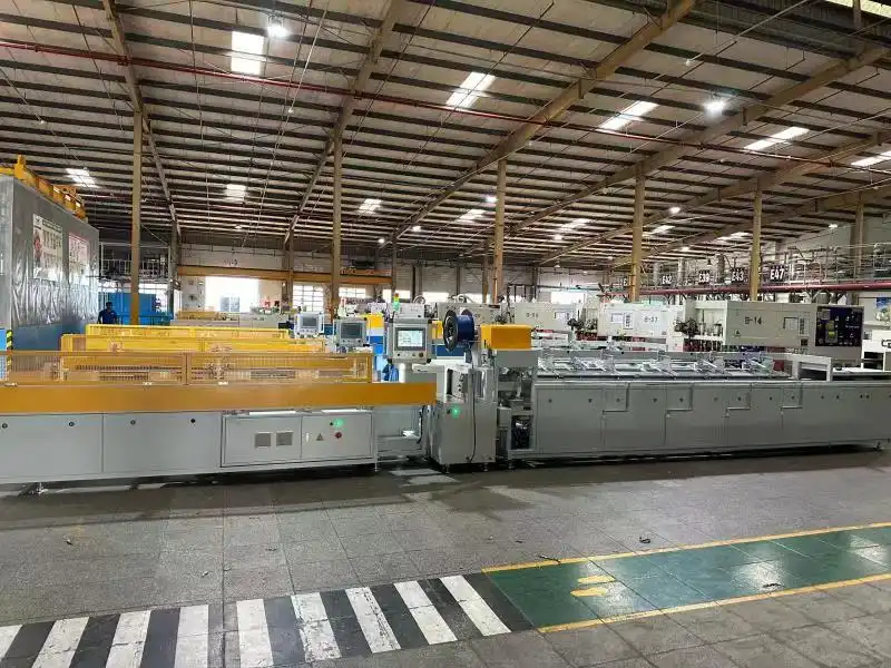
Enhancing Safety and Efficiency: Visual Management for Coil Packing Lines
Visual management is a critical component of efficient and safe operations in any industrial setting, particularly for complex systems like automated coil packing lines. By implementing clear visual cues, facilities can significantly reduce errors, improve maintenance speed, enhance safety compliance, and boost overall productivity. This guide explores key aspects of visual management, focusing on standardized pipe color-coding and effective inspection point visualization, adhering to widely recognized standards like those from ANSI/ASME and ISO. Implementing these practices ensures that personnel can quickly understand the status of equipment and processes, leading to smoother, safer operations.
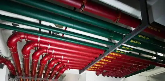
Proper color coding for piping systems is vital in industrial production for several compelling reasons:
- Enhanced Safety: Clearly identifiable pipes help personnel quickly recognize the contents (e.g., hazardous materials, high-pressure air, water), minimizing risks associated with incorrect handling or maintenance procedures.
- Improved Efficiency: Standardized markings enable maintenance and operations teams to easily locate specific pipes, saving valuable time during routine checks, troubleshooting, or emergency responses.
- Regulatory Compliance: Adhering to established color-coding standards helps facilities meet safety regulations and avoid potential penalties.
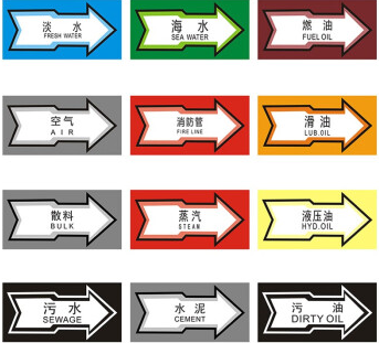
The appropriate color coding for piping systems typically follows established standards:
1. ANSI/ASME Standards
The American National Standards Institute (ANSI) and the American Society of Mechanical Engineers (ASME) publish the ASME A13.1 standard, widely adopted in the United States for pipe identification. This standard specifies color codes, label sizes, and placement to identify pipe contents and associated hazards. Key color combinations include:
- Red background / White letters: Fire Quenching Fluids (e.g., water, foam)
- Orange background / Black letters: Toxic or Corrosive Fluids (e.g., acids, alkalis)
- Yellow background / Black letters: Flammable or Oxidizing Fluids (e.g., gasoline, hydrogen)
- Brown background / White letters: Combustible Fluids (e.g., lubricating oils)
- Green background / White letters: Water (e.g., potable, cooling, boiler feed)
- Blue background / White letters: Compressed Air
Labels should also indicate the specific fluid name and flow direction. For more details, consult the official [ASME A13.1 standard].
2. International Standards (ISO)
ISO 14726 specifies a primary color-coding system used mainly in the marine and offshore industries but sometimes adopted elsewhere. It uses main colors to identify the substance group (e.g., green for seawater, grey for non-flammable gases) and color bands to specify the exact substance. Checking which standard applies to your specific region and industry is crucial. You can explore standards at the [International Organization for Standardization (ISO)].
3. National or Local Standards
Beyond ANSI/ASME and ISO, many countries or regions have specific regulations or standards for pipe marking. Always verify and comply with the requirements mandated by local industrial safety authorities or relevant governing bodies.
4. Industry Practices
Specific sectors, such as the chemical processing or oil and gas industries, often have well-established conventions or supplementary guidelines for pipe marking that may go beyond general standards. Conforming to these industry-specific practices is essential for consistency and safety within that sector.
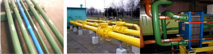
5. Visibility Considerations
When selecting and applying color codes and labels, consider the plant environment. Factors like lighting conditions, pipe location (high overhead vs. ground level), and potential for dirt accumulation can affect visibility. Ensure markings are large enough, placed conspicuously (e.g., near valves, junctions, and access points), and maintained for continued clarity.
Visualizing Equipment Inspection Points
Beyond piping, effective visual management extends to identifying and standardizing equipment inspection points. This is crucial for preventative maintenance and quick diagnostics on machinery like coil packing lines.
Effective visualization methods for equipment inspection points include:
- Numbering: Assigning unique sequential numbers to each inspection point (e.g., lubrication points, gauge checks, sensor locations). This simplifies referencing points on maintenance checklists and in digital maintenance management systems (CMMS).
- Identification Markers: Using standardized visual cues such as:
- Color-coded tags or dots: Green for routine checks, yellow for caution/monitor, red for critical checks or faults.
- Shape-coded markers: Different shapes indicating the type of inspection needed (e.g., circle for lubrication, square for pressure check, triangle for filter change).
- Clear labels: Specifying the action required (e.g., "Check Oil Level," "Inspect Belt Tension," "Verify Sensor Alignment").
- Graphical Representation: Integrating inspection point locations and numbers onto equipment diagrams or schematics. These visual aids can be posted near the machine or included in maintenance manuals for intuitive guidance.
- Landmarks/Signage: Using clear, durable signs or floor markings to guide personnel to inspection areas, especially on large or complex machinery like extensive coil packing lines. Standardized arrows or pathway markings can improve navigation.
- Standardization: Implementing a consistent methodology for marking inspection points across all similar equipment within the facility. This uniformity reduces confusion and training time, ensuring inspectors can easily understand requirements regardless of the specific machine.
Ultimately, the goal of visualizing equipment inspection points is to use clear, consistent, and intuitive marking methods. This enables maintenance personnel to quickly and accurately locate and identify each point, significantly improving the efficiency, reliability, and safety of maintenance routines on coil packing lines and other critical industrial equipment. The specific methods chosen should always be tailored to the unique characteristics of the equipment and the operational environment.