A Comprehensive Guide to Electrical Equipment and Facilities for Coil Packaging Lines
1. Core Electrical Infrastructure: Powering the Automated Line
A robust electrical infrastructure is the backbone of any efficient automated coil packaging line. A well-designed system ensures reliable power distribution and precise control over all machinery. Key components typically include:
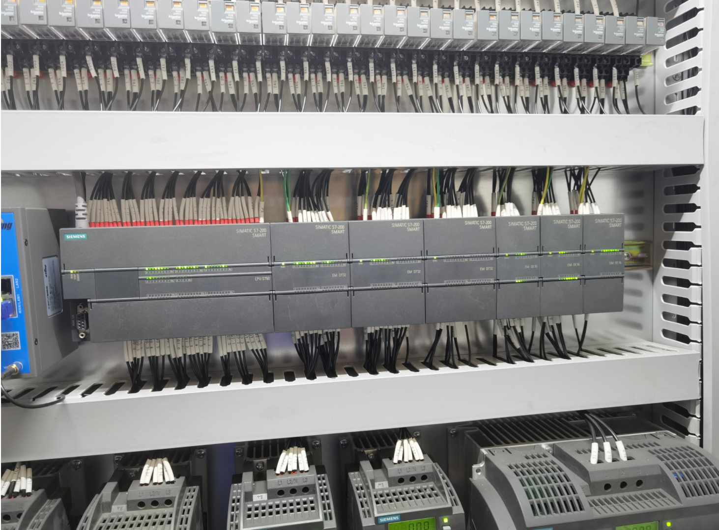
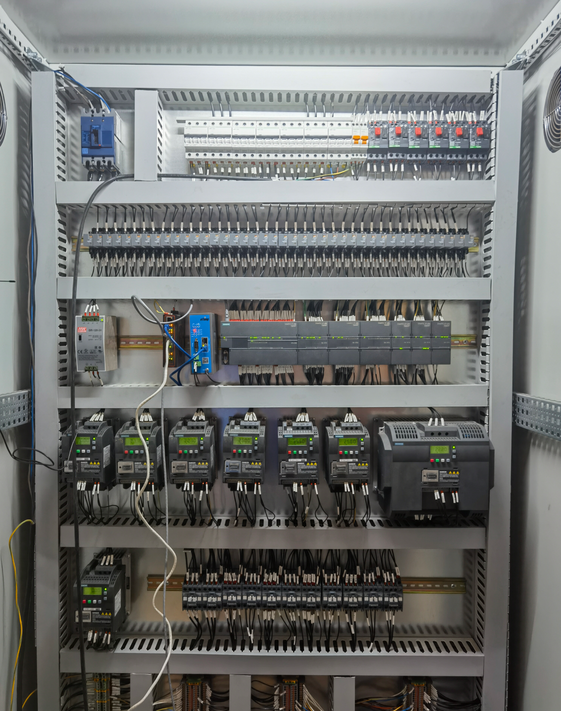
- Climate-Controlled Motor Control Center (MCC): This centralized enclosure houses critical electrical components, protecting them from environmental factors like dust, moisture, and temperature fluctuations. Maintaining a stable internal environment is essential for the longevity and reliability of sensitive electronics.
- Programmable Logic Controllers (PLCs): Acting as the "brain" of the automation system, PLCs execute pre-programmed logic to sequence operations, monitor inputs from sensors, and control output devices. They coordinate the actions of conveyors, robots, wrappers, and other equipment for seamless integration.
- Variable Frequency Drives (VFDs): VFDs provide precise control over the speed and torque of AC motors. By adjusting the frequency and voltage supplied to the motors, VFDs enable:
- Smooth start-ups and shutdowns, reducing mechanical stress.
- Accurate speed regulation for conveyors, wrappers, and robotic arms.
- Significant energy savings by matching motor speed to the required load.
- AC Motors: These are the workhorses providing the motive force for conveyors, turntables, wrapping units, and other moving parts within the automated packaging line. Proper selection and integration with VFDs are crucial for performance.
- Precision Control & Synchronization: The synergy between PLCs and VFDs allows for highly accurate control over positioning, wrapping tension, stacking sequences, and more. This precision is vital for consistent packaging quality and operational efficiency.
- Optimized Component Performance: The electrical infrastructure ensures that all critical components receive stable power and accurate control signals, allowing them to operate at peak performance and contribute to the overall throughput and reliability of the packaging line.
2. Local Push Button Control Stations: Ensuring Operator Safety and Control
Strategically placed local push button stations are essential for safe manual operation, particularly during setup, maintenance, and troubleshooting. Their key functions include:
- Enhanced Accessibility: Operators can perform adjustments, test functions, or initiate emergency stops directly at the equipment location without needing to return to the main control panel. This saves time and improves responsiveness.
- Improved Safety: Immediate access to stop buttons is critical in emergencies. Local controls allow operators to quickly halt specific machinery, mitigating risks to personnel and preventing equipment damage.
- Precise Manual Adjustments: During setup or maintenance, operators can use these stations for fine-tuning conveyor speeds, robotic movements, or other parameters, ensuring accurate operation before switching back to automated mode.
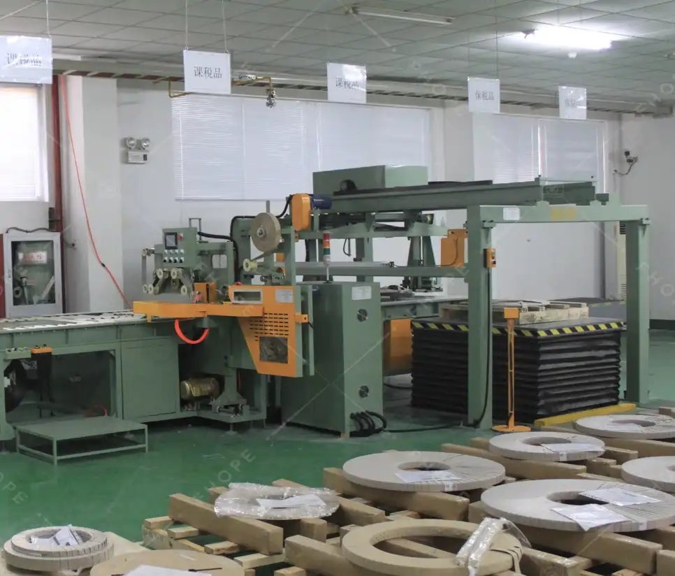
3. Local Starter Panels and Festoon Systems: Localized Power and Mobile Equipment Supply
- Local Starter Panel: This is a compact panel located near specific machinery groups.
- Function: Houses motor starters, contactors, circuit breakers, and safety relays for a particular machine or section of the line.
- Benefits: Provides localized power distribution, allows for easier troubleshooting, and enables quicker interventions or adjustments by maintenance staff. Incorporates safety features like local disconnects and emergency stops.
- Festooning Power Track Cable System: This system manages power and control cables for equipment that moves along a track or beam, common for transfer cars or certain types of overhead equipment in a packaging line.
- Function: Uses trolleys running on a track or C-rail to support and guide cables as the equipment moves, preventing entanglement and damage.
- Benefits: Ensures continuous and reliable power/control signal delivery to mobile machinery, enhances operational flexibility, and provides cable protection against wear and tear in dynamic applications.
4. Cabling Strategy: The Arteries of the System
Proper cabling is fundamental for the safe, reliable, and efficient operation of the entire coil packaging line. Key considerations include:
- Cable Specifications: Using appropriate voltage-rated (e.g., 1.1KV grade) power and control cables is essential. Power cables deliver energy to motors and devices, while control cables transmit signals between PLCs, sensors, actuators, and control panels.
- Cable Management:
- Cable Trays and Conduits: These provide organized pathways for cables, protecting them from physical damage, environmental factors, and electromagnetic interference. They ensure a clean installation and simplify future maintenance or expansion.
- Accessories: Using correct cable glands (for sealing entry points), lugs (for secure termination), tags (for identification), and termination kits is crucial for reliable connections and safety.
- Installation Best Practices:
- Segregation: Separate power and control cables where necessary to prevent interference.
- Labeling: Clearly label all cables at both ends for easy identification during troubleshooting and maintenance.
- Documentation: Maintain accurate drawings and documentation of cable routes.
- Compliance: Adhere strictly to relevant industry standards and electrical codes (e.g., NEC, IEC) for installation practices.
The cabling approach for a robust packaging line should emphasize:
- Correct Sizing and Selection: Choose cables, trays, and conduits appropriate for the electrical load, environmental conditions, and physical layout.
- Standards Adherence: Ensure all installation practices meet or exceed local and international electrical safety standards.
- Scalability: Design the cabling infrastructure with future expansion or modifications in mind.
5. Grounding and Lightning Protection: Ensuring Safety and Reliability
Effective grounding (earthing) and lightning protection are non-negotiable safety requirements for any industrial installation, including coil packaging lines.
- Equipment Grounding:
- Purpose: Provides a safe path for fault currents (e.g., from short circuits) to flow to the earth, minimizing the risk of electric shock to personnel and preventing damage to equipment.
- Scope: All metallic components of the packaging line, including machine frames, control panels, motors, conveyors, and support structures, must be properly bonded and connected to the facility's grounding system.
- Static Discharge: Grounding also helps dissipate static electricity that can build up during material handling, reducing potential ignition hazards or interference with electronics.
- Lightning Protection System:
- Purpose: Protects the facility and sensitive electronic equipment (PLCs, VFDs, sensors) from damage caused by direct lightning strikes or lightning-induced power surges.
- Components: Typically involves air terminals (lightning rods), down conductors, and a dedicated grounding electrode system designed to safely conduct high-energy lightning currents to the earth.
- Surge Protection: Implementing Surge Protective Devices (SPDs) at key points in the electrical distribution system is crucial to guard against transient overvoltages entering through power or communication lines.
6. Essential Erection and Installation Materials
The quality and correct application of installation materials directly impact the safety, reliability, and longevity of the electrical system.
- Cable Glands: Secure cables entering enclosures (panels, junction boxes), providing strain relief and environmental sealing (IP rating) against dust and moisture.
- Lugs: Used to terminate cables onto bus bars, circuit breakers, or equipment terminals, ensuring a low-resistance, secure electrical connection. Proper crimping is essential.
- Tags/Markers: Essential for labeling cables, wires, and components for clear identification, facilitating maintenance and troubleshooting.
- Termination Kits: Contain all necessary components (lugs, insulation, sealing materials) for properly terminating medium or high-voltage cables, ensuring electrical integrity and safety.
- Cable Trays and Conduits: Provide mechanical support and protection for cables (as detailed in Section 4). Material selection (e.g., galvanized steel, aluminum, PVC) depends on the environment.
- Compatibility: Ensure all installation materials (glands, lugs, etc.) are correctly sized and rated for the specific cables and application environment they are used in.
7. Battery Limit Considerations and Electrical Building Design
The "battery limit" defines the boundary of a specific operational unit or project scope. When designing the electrical infrastructure for a coil packaging line within a defined battery limit, several factors are critical:
- Electrical Building/Room: Often, a dedicated, climate-controlled electrical building or room is established within the battery limit to house the main MCC, PLCs, VFDs, and distribution panels.
- Layout Optimization: The design must efficiently accommodate all necessary equipment while ensuring adequate working space for maintenance personnel, adhering to safety regulations.
- Environmental Control: HVAC systems are crucial to maintain optimal temperature and humidity levels for sensitive electronic equipment.
- Cable Engineering and Routing:
- Planning: Detailed planning of cable routes from the electrical room to all equipment within the battery limit is essential. This includes pathways through trenches, conduits, and cable trays.
- Segregation and Protection: Maintain proper separation between power, control, and communication cables. Ensure routes avoid high-traffic areas or sources of potential damage.
- Emergency Systems Integration: Incorporate essential safety and backup systems within the electrical design:
- Emergency Lighting: Ensure adequate illumination during power outages.
- Fire Detection and Suppression: Integrate appropriate systems for the electrical room and key equipment areas.
- Uninterruptible Power Supply (UPS): Provide backup power for critical control systems (PLCs, safety circuits) to allow for controlled shutdowns or continued operation during brief power dips.
- Scalability and Documentation: Design the system with potential future expansion in mind. Maintain comprehensive and accurate documentation (drawings, schematics, cable schedules) for the entire electrical installation within the battery limit.
By carefully planning and implementing these electrical systems and facilities, manufacturers can ensure their coil packaging lines operate safely, efficiently, and reliably, contributing significantly to overall productivity and product quality.