Optimizing Welding Standards for Positioner Flipping Machines
1. Introduction: The Role of Welding Standards in Automated Fabrication
Positioner flipping machines are instrumental in modern fabrication, enabling welders to manipulate complex workpieces for optimal joint access and consistent weld quality. However, the effectiveness of these machines hinges on the application of precise welding standards. Establishing and adhering to appropriate parameters is crucial for preventing common welding defects like burn-through, incomplete penetration, and porosity, particularly when working with materials susceptible to thermal distortion, such as thin sheets. This guide explores essential welding standards for positioner flipping machines, focusing on parameter control, stability, and defect prevention to achieve robust, high-quality welds.

2. Why Precise Welding Standards Matter for Positioner Flipping Machines
Utilizing a positioner flipping machine allows for automated or semi-automated welding processes, enhancing efficiency and ergonomics. However, automation demands consistency. Minor deviations in welding parameters can have significant consequences:
- Insufficient Penetration: Low heat input (often due to low current or voltage) can result in weak welds that fail to fuse the base materials properly.
- Burn-Through: Excessive heat input can melt through the material, creating holes, especially problematic in thinner sections.
- Structural Integrity: Both defects compromise the weld's strength and the finished product's structural integrity, potentially leading to failures, costly rework, or rejection.
The challenge intensifies when welding thin materials. For instance, in automatic welding of materials around 3 mm thick, the acceptable window for weld penetration depth (n1) is extremely narrow. If n1 is below approximately 1.5 mm, incomplete penetration is likely. Conversely, exceeding 2.0 mm often results in burn-through. This tight tolerance (less than 1 mm) necessitates strict control over welding parameters when using positioner flipping machines.
3. Understanding Key Welding Parameters and Their Impact
Achieving optimal weld quality requires careful management of several interconnected welding parameters. While specific values depend heavily on the material type, thickness, joint design, welding process (e.g., GMAW, FCAW, SAW), and shielding gas, understanding the role of each is fundamental:
- Welding Current (Amperage): Primarily controls the melting rate of the electrode (wire) and influences the depth of penetration. Higher current generally means deeper penetration and faster wire feed speed.
- Voltage (Arc Voltage): Affects the arc length and the width/profile of the weld bead. Higher voltage typically produces a flatter, wider bead and can increase susceptibility to spatter or undercut if not balanced with current and travel speed.
- Travel Speed: The speed at which the welding torch moves along the joint. It influences heat input per unit length; slower speeds increase heat input and penetration, while faster speeds decrease them.
- Wire Feed Speed (WFS): Directly related to current in constant voltage processes (like GMAW). Controls the amount of filler metal deposited. Must be balanced with current and travel speed for proper bead formation.
- Shielding Gas: Protects the molten weld pool from atmospheric contamination. The type of gas (e.g., CO2, Argon mixtures) affects arc stability, penetration profile, and weld appearance.
4. Parameter Considerations for Thin Materials (Example: 3mm Thickness)
Welding thin materials requires a delicate balance to achieve sufficient fusion without excessive heat input. While universal settings are impossible, the principles behind parameter selection are key. Using φ1.6 mm wire as an illustrative example (parameters will vary significantly based on actual process and wire diameter):
4.1. Main Seam Welding Parameters
For the primary weld seams on materials around 3mm, a lower current range is often preferred to minimize heat input and reduce distortion or burn-through risk.
- Example Current Range (I1): 160A - 200A
- Lower End (e.g., 160A): Minimizes heat, suitable for very thin sections or heat-sensitive materials, but requires careful control to ensure adequate penetration.
- Higher End (e.g., 200A): Provides more robust penetration, potentially needed for slightly thicker sections within the "thin" category or specific joint types, but increases burn-through risk.
4.2. Root Pass or Sealing Pass Parameters
Root passes often require sufficient energy to ensure complete fusion at the joint root.
- Example Current Range (I2): 220A - 280A
- This higher range aims for full penetration. However, excessive current here is a primary cause of burn-through on thin materials. Careful adjustment and potentially using techniques like pulse welding can help manage heat input.
Important Note: These current ranges are examples and highly dependent on the specific welding process (GMAW, FCAW, etc.), shielding gas, wire type/diameter, and material. Developing a specific Welding Procedure Specification (WPS) through testing is essential for any application.

5. The Critical Role of Parameter Stability
For consistent results, especially in automated setups using positioner flipping machines and when welding thin materials, stability is paramount.
- High Stability Requirement: Even minor fluctuations in current or voltage during welding can lead to inconsistent penetration, bead profile variations, and increased porosity.
- Control Tolerances: Aim for minimal variation. Ideally:
- Current Fluctuation: Within ±10A of the setpoint.
- Voltage Fluctuation: Within ±2V of the setpoint.
- Consistent Heat Input: Stable parameters ensure uniform heat input along the weld length. This is vital for predictable penetration and minimizes the risk of trapping gases, which causes porosity. Advanced power sources and controllers on modern positioner systems help achieve this stability.
6. Preventing Common Welding Defects with Positioners
Meticulous parameter control and stable operation are key to avoiding defects:
- Burn-Through:
- Cause: Excessive heat input (high current/voltage, slow travel speed).
- Prevention: Reduce current/voltage, increase travel speed, use appropriate technique (e.g., weaving, pulse modes), ensure proper fit-up. Use the lower end of appropriate parameter ranges for thin sections.
- Incomplete Penetration (Lack of Fusion):
- Cause: Insufficient heat input (low current/voltage, fast travel speed), incorrect torch angle, inadequate joint preparation.
- Prevention: Increase current/voltage appropriately, decrease travel speed, ensure correct torch angle and work angle facilitated by the positioner, properly clean and prepare the joint. Ensure root pass parameters provide adequate energy.
- Porosity:
- Cause: Gas trapped in the weld metal (atmospheric contamination, impurities on base metal/filler wire, inadequate shielding gas coverage, excessive voltage/arc length, inconsistent heat input).
- Prevention: Ensure adequate shielding gas flow rate and coverage, check for leaks in gas lines, use clean/dry materials and consumables, maintain stable and correct parameters (avoid excessive voltage), ensure consistent heat input.
- Undercut:
- Cause: Groove melted into the base metal next to the weld toe, reducing cross-sectional thickness. Often caused by excessive current/voltage or incorrect torch angle.
- Prevention: Optimize voltage and current settings, adjust torch angle, use appropriate travel speed.
- Overlap:
- Cause: Weld metal protruding beyond the weld toe or root without fusing to the base metal. Often caused by insufficient heat input or slow travel speed relative to deposition rate.
- Prevention: Increase travel speed, adjust parameters for better fusion (potentially higher current/voltage, carefully balanced), ensure correct torch positioning.

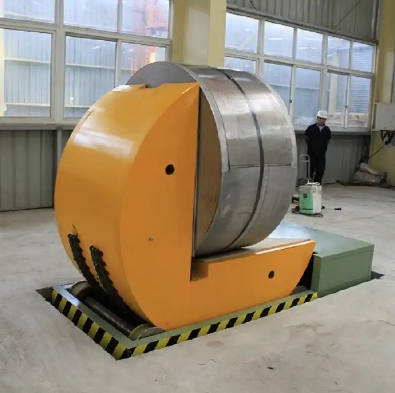
hydraulic tilter and upender for turning4 7. Best Practices for Implementing Welding Standards
To leverage positioner flipping machines effectively and ensure consistent weld quality:
- Develop Welding Procedure Specifications (WPS): Conduct thorough testing to determine the optimal parameters (current, voltage, travel speed, gas flow, etc.) for each specific application (material, thickness, joint type). Document these in a formal WPS.
- Use Qualified Procedures and Personnel: Ensure welding procedures are qualified according to relevant codes (e.g., AWS D1.1 for structural steel) and that operators or welding programmers are properly trained and qualified.
- Regular Equipment Calibration and Maintenance: Ensure the welding power source, wire feeder, and the positioner flipping machine itself are regularly calibrated and maintained. This guarantees that set parameters accurately reflect the actual output, ensuring stability and consistency.
- Leverage Automation and Monitoring: Utilize the features of modern positioner systems, which may include real-time monitoring and feedback loops that can adjust parameters automatically to compensate for minor variations, ensuring consistent heat input.
- Prioritize Joint Preparation and Fit-up: Consistent and accurate joint preparation and fit-up are crucial. Poor fit-up requires excessive weld metal or makes achieving consistent penetration difficult, even with perfect parameters.
- Consult Authoritative Resources: For detailed guidance on welding parameters, defect analysis, and procedure qualification, refer to standards bodies and technical organizations like the American Welding Society (AWS).
coil tilter upender44 8. Conclusion: Precision Parameters for Reliable Fabrication
Effective welding standards are non-negotiable when using positioner flipping machines, particularly for demanding applications like welding thin materials. Precise control over welding current, voltage, travel speed, and ensuring parameter stability are fundamental to preventing defects such as burn-through, incomplete penetration, and porosity. By establishing robust Welding Procedure Specifications based on thorough testing, maintaining equipment calibration, and leveraging the capabilities of modern positioning and welding technology, fabricators can achieve consistently high-quality, structurally sound welds that meet stringent industry requirements. Adherence to these standards translates directly to improved productivity, reduced rework, and enhanced product reliability.
Get Your Best Solution !