The Ultimate Guide to Coil Wrapping Machines: Types, Components, and Operation
Coil wrapping machines are essential equipment in industries dealing with coiled materials like steel, copper wire, aluminum, and cables. They provide automated solutions for securely packaging these often heavy and bulky items, protecting them from environmental factors like dust and moisture, and preventing damage during handling, storage, and transportation. Understanding the different types of coil wrappers available is crucial for selecting the right solution for specific operational needs.
Coil wrapping machines generally fall into two main categories based on the coil's orientation during wrapping:
- Vertical Coil Wrapping Machines: Designed for coils positioned with the eye (center hole) facing the wall (vertical axis). Loading can be manual for smaller coils or via crane for heavier ones.
- Horizontal Coil Wrapping Machines: Intended for coils lying flat with the eye facing the sky (horizontal axis). These machines typically use stretch film to wrap the coil securely.
This guide explores various types of coil wrapping machines, detailing their components and operational processes.
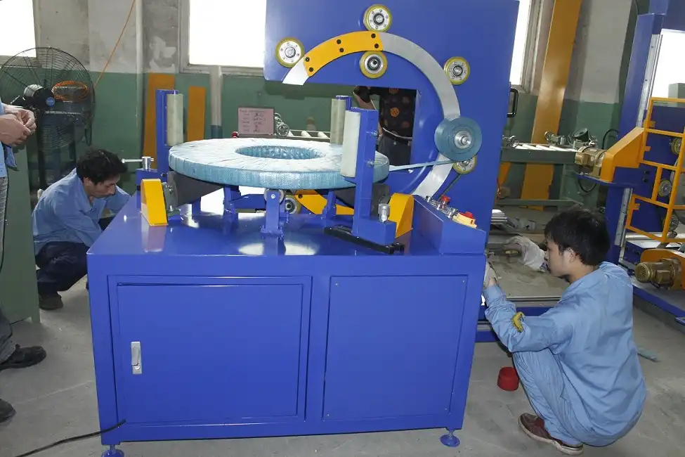
1. Semi-Automatic Vertical Coil Wrapping Machine
This type of machine wraps coils positioned vertically (eye-to-wall).
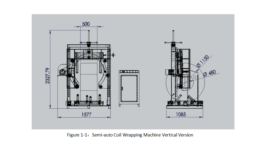
Figure 1-1: Semi-Automatic Vertical Coil Wrapping Machine
1.1 Key Components:
- (1) Frame: The main structural base of the machine.
- (2) Driven Wheels: Circularly arranged wheels that rotate the coiling ring.
- (3) Coiling Ring: A rotating ring with an adjustable opening for the coil to pass through; carries the wrapping material.
- (4) Support Wheels: Side wheels providing stability to the coiling ring.
- (5, 6, 7) Grooves and Protrusions: Interlocking design features ensuring smooth rotation between driven wheels and the coiling ring.
- (8, 9) Motors: Power the driven wheels (ring rotation) and the ring height adjustment system.
- (10) Support Ring: A stationary ring guiding the driven wheels.
- (11) Support Pillar: Vertical post holding the second motor and supporting the structure.
- (12) Main Rod & (13) Driven Rod: Connect to the motor for vertical movement (height adjustment) of the coiling ring.
- (14) Clamp: Secures the support ring, allowing for adjustments.
- (15, 16, 17) Support Columns: Vertical supports holding the coil in place.
- (18) Rollers: Positioned between support columns to stabilize the coil during wrapping.
1.2 Operating Principle:
1.2.1 Basic Structure:
The machine features a robust frame supporting circularly arranged driven wheels. The coiling ring rests on these wheels. The steel coil passes through the adjustable opening in the ring, which rotates to apply the wrapping material.
1.2.2 Support and Movement:
Grooved support wheels secure the ring during operation. A motor powers the driven wheels, rotating the ring at an adjustable speed. The interlocking grooves and protrusions ensure smooth, stable rotation as the ring dispenses packing material through the coil's eye. The friction between the wheels and the ring can be adjusted by repositioning the wheels.
1.2.3 Height Adjustment:
A lifting mechanism, controlled by a second motor via a gear system connected to the main and driven rods, adjusts the coiling ring's height. This accommodates coils of different outer diameters (OD), ensuring the wrapping process is centered and precise.
1.2.4 Coil Support:
The coil rests on a base featuring one top support roller and two base supportive rollers. These rollers provide stability and hold the coil firmly during the wrapping cycle.
1.2.5 Efficient Wrapping:
This design ensures coils are wrapped tightly and efficiently, offering protection against environmental elements and handling stresses.
2. Semi-Automatic Horizontal Coil Wrapping Machine
This machine wraps coils positioned horizontally (eye-to-sky).

Figure 2-1: Semi-Automatic Horizontal Coil Wrapping Machine
The machine securely holds the coil between powered rollers and pressure rollers. The powered rollers rotate the coil while an open rotating ring applies the wrapping material (like stretch film or tape). This setup prevents deformation or instability during wrapping, ensuring an even, tight package.
2.1 Key Components:
- (1) Frame: The main machine structure.
- (2) Open Rotating Ring: Mounted on the frame, rotates to apply wrapping material.
- (3) Material Holder: Attached to the rotating ring, holds the wrapping material roll.
- (4-6) Support Wheels: Guide the rotating ring.
- (7) Powered Rollers: Positioned on either side of the ring, rotate the coil; connected to a drive mechanism.
- (8) Pressure Rollers: Located above powered rollers, movable (via cylinders) to press down and stabilize the coil.
- (9) Cylinder: Actuates the pressure rollers.
- (10) Motor: Drives the coil rotation (powered rollers) and ring rotation.
2.2 System Details:
- The drive mechanism typically includes a motor mounted on the frame, powering the rollers via a timing belt.
- Pressure rollers are connected to the frame via cylinders, allowing adjustable pressure.
- A PLC (Programmable Logic Controller) often controls the motors and cylinders for precise, automated operation sequences.
2.3 Wrapping Process:
- The coil (or similar round object like a tire) is placed onto the powered rollers.
- Cylinders lower the pressure rollers to clamp the item securely.
- The PLC ensures appropriate clamping pressure.
- Wrapping material is attached to the item.
- The open rotating ring spins, applying the material, while the powered rollers simultaneously rotate the coil.
- This coordinated movement results in an even, tight wrap around the entire coil surface.
This design ensures efficient wrapping with consistent tension, preventing product movement or damage during the process.
3. Vertical Coil Wrapper with Trolley
This automated vertical wrapper utilizes a trolley system for loading and unloading, ideal for heavy metal coils like steel, wire, and copper. The trolley moves the coil into and out of the wrapping station, separating the loading area from the wrapping zone.

Figure 3-1: Vertical Coil Wrapping Machine with Trolley
3.1 Key Components:
- (1) Gantry Frame: The main overhead structure.
- (2) Moving Rails: Guide the trolley carriage at the base.
- (3) Wrapping Device: The ring mechanism that applies wrapping material, mounted on the lifting system.
- (4) Lifting Device: Moves the wrapping device vertically to match the coil's center height.
- (5) Trolley Carriage: Moves along the rails (powered by motor/gear), transporting coils; equipped with positioning sensors.
- (6) Carriage Drive System: Powers the trolley's movement.
- (7) Supportive Roller & (8) Supportive Roller: Located on the trolley, support and rotate the coil during wrapping (often driven).
- (9) Power Wheel: Motor-driven wheel under the trolley for movement along rails.
- (10) Ring Driving Wheels: Transmit power (from a motor) to rotate the wrapping ring.
- (11) Shield: Safety guarding around the ring and material path.
- (12) Side Rollers: Positioned on the trolley to secure the coil laterally.
3.2 Implementation Details:
The robust gantry frame supports the lifting device, which uses chains/sprockets driven by a motor to adjust the wrapping device's height precisely to the coil's center.
The trolley carriage moves along rails via its drive system. Supportive rollers on the trolley, each potentially powered by its own motor, rotate the coil. Side rollers prevent lateral shifting and can adjust for different coil widths.
3.3 Wrapping Process:
- Loading: A coil (A) is loaded by crane onto the supportive rollers on the trolley (while it's outside the wrapping station). The ring adjusts height, and rollers position to hold the coil.
- Wrapping Coil A: The trolley moves coil A into the wrapping station. The supportive rollers rotate the coil while the wrapping device applies the material.
- Automatic Cutting: The machine automatically measures and cuts the wrapping material based on pre-set parameters (coil size) in the Human-Machine Interface (HMI).
- Loading Coil B: While coil A is wrapping, the next coil (B) can be loaded onto the waiting supportive rollers on the other end of the trolley or a secondary loading position.
- Continuous Operation: Once coil A is wrapped, the trolley moves it out, and simultaneously moves coil B into the wrapping position. A third coil can then be loaded. This allows for a continuous, highly efficient automated workflow.
The entire system is typically managed by an automated control system using PLCs and photoelectric sensors for accurate coil positioning and seamless operation, minimizing manual intervention.
4. Automatic Horizontal Stretch Wrapper
This type of machine focuses on automating the film feeding and cutting process for wrapping horizontal coils, particularly suited for integration into production lines.

Figure 4-1: Automatic Horizontal Stretch Wrapper with Film Feed/Cut System
This system streamlines wrapping by eliminating manual film handling, boosting production speed and ensuring consistent wrap quality, crucial for high-volume industrial applications.
4.1 Key Components (Figure 4-1):
- (1) Main Board: Base structure for mounting components.
- (2) Guiding Wheel Assembly: Guides the wrapping material path.
- (3) Automatic Cutting Mechanism: Cuts the film/tape after wrapping.
- (4) Automatic Band Feeding Arm: Rotates to feed the material into the ring.
- (5) Open Rotating Ring: Applies the wrapping material around the coil.
- (6) Material Feeding Unit: Holds and dispenses the wrapping material roll.
- (7) Conveying Wheels: Assist material movement around the ring.
- (8) Rotary Drive Unit: Powers the rotation of the ring.
- (9-15) Associated Mechanical Parts: Connecting rods, bearings, sleeves, blocks enabling movement and function.
4.2 System Configuration:
The material feeding unit supplies wrapping tape/film, guided through the guiding wheel assembly towards the open rotating ring. The automatic cutting mechanism is typically below the main board, while the automatic feeding arm is positioned above, designed to rotate and position the material correctly for starting the wrap cycle.
4.3 Wrapping Process (Automated Feed/Cut):

Figure 4-2: Wrapping Process Illustration
- The product (coil) moves into the wrapping position (e.g., via conveyor or rotary support). Wrapping material is held by the automatic cutting mechanism.
- The system starts: the automatic feeding arm rotates (driven by cylinder/connecting rod) and guides the material end into the open rotating ring area.
- The rotating ring starts turning slowly (driven by friction wheels). As it passes through the coil's eye, the material begins wrapping around the conveying wheels.
- The ring continues rotating, pulling the material around the product. The feeding arm moves away slightly.
- Once a few layers are applied, a clamping mechanism releases the material end from the feeding arm.
- The ring speeds up for the main wrapping cycle. When the required amount of material is applied, the ring stops. The automatic feeding arm returns to its start position, the clamping mechanism resets to hold the material end, and the cutting mechanism cuts the material. The wrapped coil is then ready to be moved out.
4.4 Key Features & Advantages:
- Automated Material Handling: Automatic feeding and cutting eliminates manual steps.
- Efficiency: Reduces cycle times and labor requirements.
- Consistency: Ensures uniform wrapping quality and material usage.
- Safety: Minimizes operator interaction with moving parts.
- Preferred Setup: Often uses pneumatic shears for cutting and precisely controlled actuators (cylinders, motors) for the feeding arm movement.
This automated system is ideal for integrating coil wrapping into continuous production lines, enhancing throughput and safety.
5. Master Coil Wrapper
Master coil wrappers are heavy-duty machines designed for packaging very large and heavy coils, such as those found in metal service centers and mills.
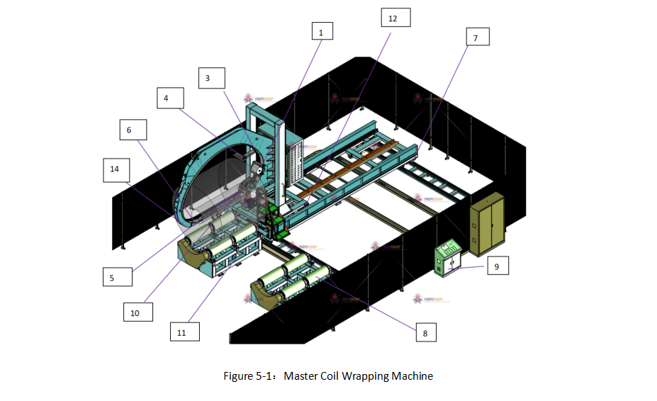
Figure 5-1: Master Coil Wrapping Machine
5.1 Component Overview:
- (1) Tape Dispensers: One or more units applying wrapping material.
- (2) Flexible Orbital: A track (often chain or belt) guiding the tape dispensers around the coil.
- (3) Frame/Arch: The main structure encompassing the wrapping area.
- (4) Material Holder: Supports the rolls of wrapping material.
- (5) Traction Unit: Drives the flexible orbital (often located outside the arch for accessibility).
- (6) Bridge Section: Part of the frame/arch that opens for coil loading/unloading.
- (7) Mobile Support Cart/Trolley (12): Transports the coil into/out of the wrapping station along tracks.
- (8) Support Rolls: Located on the cart, rotate the coil during wrapping.
- (9) Control System: Coordinates all machine movements and parameters.
- (10) Servos: Motors providing precise control over movements.
- (11) Platform: The rotating base on the cart supporting the coil.
- (13) Position Sensors: Detect coil/trolley location for automation.
- (14) Locking Mechanism: Secures the flexible orbital/bridge during operation.
- (15) Chain or Belt: The element comprising the flexible orbital.
5.2 Detailed Operation and Design:
Master coil wrappers utilize tape dispensers mounted on a carriage that travels along a flexible orbital (chain or belt) guided by the machine's frame/arch. This orbital system wraps material tightly around the large coil. Low-friction designs for the orbital ensure smooth movement and reliability.
5.3 Bridge and Loading System:
A key feature is the openable bridge section of the frame/arch, allowing large coils to be loaded/unloaded efficiently. This bridge can open hydraulically, pneumatically, or electrically, often retracting to provide clear access. After loading/unloading, the bridge closes, and the flexible orbital re-engages automatically.
Coils are typically transported by a mobile support cart (trolley) moving on rails. The coil rests on powered support rolls on the cart, which rotate it during wrapping to ensure even material application.
5.4 Control and Synchronization:
A sophisticated control system (often PLC-based with an HMI) synchronizes the orbital speed, coil rotation speed, trolley movement, and bridge operation. Operators can set parameters for wrap overlap, tension, and cycle steps. Servos and sensors ensure precise positioning and locking of components like the bridge and orbital before and during wrapping.
5.5 Versatility and Application:
While primarily used for large metal coils, the principle can apply to other large, heavy cylindrical or toroidal products. The synchronized rotation of the coil and movement of the wrapping head ensures a consistent, slightly overlapping wrap for full protection. The wrapping station itself might be mounted on a trolley for precise alignment.
5.6 Enhanced Automation:
Position sensors on the trolley track the coil's location, enabling automated stopping at loading, wrapping, and unloading points. Locking mechanisms ensure the flexible orbital and bridge are securely fastened during the high-speed wrapping process, enhancing safety and operational integrity.
Conclusion
Coil wrapping machines are vital for protecting valuable coiled products across various industries. From semi-automatic vertical and horizontal units suitable for diverse coil sizes and weights to fully automated systems with trolley loading and automatic film handling, the technology offers significant benefits in efficiency, product protection, and labor savings. Master coil wrappers cater specifically to the demands of handling very large, heavy coils in industrial settings. Understanding the specific features, components, and operating principles of each type allows businesses to select the optimal coil packaging solution to meet their production requirements and ensure product integrity throughout the supply chain.