Comprehensive Guide to Load Analysis for Roller Conveyor Systems
1. Introduction: Why Load Analysis Matters
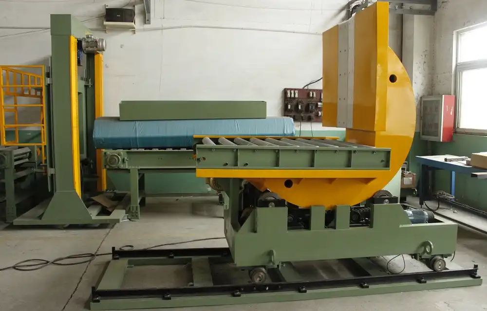
Roller conveyor systems are fundamental components in modern logistics, manufacturing, and distribution centers, enabling the streamlined movement of goods. However, operating these systems beyond their designed load capacity—a condition known as overload—can severely compromise their performance and longevity. Overloading introduces excessive strain on critical mechanical parts like rollers, bearings, motors, and frames, leading to premature wear, unexpected breakdowns, and potential safety hazards. This guide provides a comprehensive load analysis of roller conveyor systems, exploring the causes and effects of overload, the technologies used for monitoring, and strategies for prevention. Understanding and implementing effective load management is crucial for ensuring the reliability, efficiency, and safety of your conveyor operations.
2. Understanding Overload in Roller Conveyor Systems
Overload occurs when the weight, size, or distribution of items on a conveyor exceeds the system's specified limits. It's not just about the maximum weight capacity; factors like load concentration and impact forces during loading also contribute.
2.1. Common Causes of Conveyor Overload
- Exceeding Weight Limits: Loading items heavier than the per-roller or total system capacity.
- Poor Load Distribution: Concentrating weight on a small section of the conveyor instead of spreading it evenly.
- Accumulation: Bottlenecks downstream causing items to pile up on the conveyor, increasing the static load.
- Impact Loads: Dropping heavy items onto the conveyor instead of loading them smoothly.
- System Misconfiguration: Using a conveyor not rated for the specific application or load type.
2.2. Consequences of Overloading
Ignoring load limits can lead to significant operational and financial repercussions:
- Accelerated Wear and Tear: Bearings seize, rollers deform, belts stretch or tear, and drive components (motors, gearboxes) experience excessive strain, drastically reducing their service life.
- Mechanical Failures & Downtime: Components break, leading to sudden system halts, costly emergency repairs, and lost production time.
- Decreased Efficiency: Overloaded systems often run slower, consume more energy, and may struggle to maintain consistent material flow.
- Safety Hazards: Structural failure or dropped loads can pose serious risks to personnel working near the conveyor. Refer to safety guidelines from organizations like OSHA for conveyor safety standards.
- Product Damage: Items can be damaged due to abrupt stops, falls, or crushing from accumulation.

3. Load Monitoring Systems and Safety Mechanisms
Modern conveyor systems often integrate sophisticated load monitoring technologies and safety protocols to mitigate the risks associated with overload conditions.
3.1. Real-Time Load Monitoring Technologies
Sensors and control systems continuously track load conditions, providing data for immediate action or long-term analysis. Key technologies include:
- Load Cells: Integrated into conveyor sections or support structures, these sensors directly measure the weight on the conveyor.
- Motor Current Monitoring: Tracking the electrical current drawn by the drive motor. An abnormally high current often indicates excessive load.
- Torque Sensors: Measuring the torque required to drive the conveyor, which correlates directly with the load.
- Vision Systems/Photo Eyes: Detecting product accumulation or unusually large items that could indicate overload or blockage.
3.2. Protective Responses to Overload Detection
When monitoring systems detect an overload, automated responses can prevent damage:
- Warning Signals (Minor/Moderate Overload): Visual alarms (lights) or audible signals alert operators to a potential issue, allowing manual intervention like reducing feed rate or redistributing load.
- Automatic Shutdown (Severe Overload): If the load exceeds critical thresholds, the control system can immediately stop the conveyor (and potentially upstream feeders) to prevent catastrophic failure. This protects the motor, gearbox, and structural components from extreme stress.
- Torque Limiters/Safety Clutches: Mechanical devices (like shear pins or electronically controlled clutches) that disengage the drive motor from the conveyor when torque exceeds a safe level.
Implementing these safety mechanisms is vital for protecting equipment investment and ensuring workplace safety.
4. The Role of Sensor Technology in Detailed Load Analysis
Sensor technology is the cornerstone of effective conveyor load analysis, providing the raw data needed to understand operational stresses.
4.1. Key Sensor Types and Their Functions
- Strain Gauges/Load Cells: Directly measure weight and force by detecting minute deformations in structural components or dedicated measuring devices. Highly accurate for static and dynamic load measurement.
- Tension Sensors: Primarily used in belt conveyors, they monitor belt tension, which increases with load. Also relevant in certain roller applications where chain tension is monitored.
- Vibration Sensors (Accelerometers): Detect abnormal vibrations caused by failing bearings, roller imbalances, or excessive structural stress, often exacerbated by overloading. Useful for predictive maintenance.
- Proximity Sensors/Photo Eyes: Monitor product flow, detect gaps, and identify accumulation zones which contribute to localized overloads.
The selection and placement of sensors depend on the conveyor type, application, and specific monitoring goals. Consulting resources from sensor manufacturers or engineering bodies like the American Society of Mechanical Engineers (ASME) can provide further guidance.
5. Data Collection and Signal Processing for Load Insights
Raw data from sensors requires processing to become actionable intelligence for load analysis and system control.
5.1. The Data Processing Workflow
- Signal Conditioning: Sensor outputs (often analog voltages or resistances) are converted into standardized electrical signals.
- Amplification and Filtering: Weak signals are amplified for accuracy, and electrical noise (interference) is filtered out to prevent false readings.
- Analog-to-Digital Conversion (ADC): Conditioned analog signals are converted into digital format for computer processing.
- Data Acquisition (DAQ): A DAQ system collects the digitized data from multiple sensors simultaneously.
- Analysis and Visualization: Software processes the digital data, performs calculations (e.g., total load, peak load, load distribution), displays real-time conditions, logs historical trends, and triggers alarms based on pre-set thresholds.
6. Leveraging Conveyor Load Data for Enhanced Operations
Analyzing collected load data offers significant opportunities for operational improvement beyond simple overload prevention.
6.1. Process Optimization Insights
Historical load data can reveal patterns associated with specific products, shifts, or operational procedures. This allows for informed decisions:
- Identifying peak load times and adjusting workflows to smooth out demand.
- Optimizing product spacing or batch sizes to prevent accumulation.
- Pinpointing bottlenecks in the material handling process.
- Validating that system modifications achieve the desired load distribution.
6.2. Enabling Predictive Maintenance
Consistent monitoring, especially incorporating vibration and motor current data alongside direct load measurements, facilitates predictive maintenance (PdM):
- Tracking gradual increases in vibration or motor current under normal loads can indicate developing bearing failure or increased friction.
- Correlating load history with component lifespan helps predict when replacements will be needed based on actual usage intensity, not just fixed schedules.
- Scheduling maintenance proactively based on data-driven predictions minimizes unplanned downtime and reduces overall maintenance costs compared to reactive or purely time-based strategies.

7. Directional Control Considerations in Load Management
While load capacity is primary, the ability to control movement direction is also crucial, especially in systems requiring bi-directional flow or precise positioning.
7.1. Importance of Bi-Directional Control
Many applications, such as loading/unloading stations or reversible process lines, require conveyors to run reliably in both forward and reverse. This capability, usually provided by the motor and control system via a gearbox, enhances operational flexibility.
7.2. Achieving Smooth Direction Changes Under Load
Reversing direction, especially with a significant load, introduces dynamic forces. Smooth control is essential:
- Ramped Acceleration/Deceleration: Variable Frequency Drives (VFDs) allow gradual speed changes, reducing jerks and stress on components during starts, stops, and reversals.
- Braking Systems: Effective braking (mechanical or electrical via the VFD) ensures controlled stops, preventing load shifting or coasting.
- Integrated Controls: Tying directional control logic with load monitoring ensures that direction changes don't occur under potentially damaging overload conditions.
8. Designing Roller Conveyors for Robust Overload Protection
Proactive overload protection starts with robust conveyor design, anticipating potential stresses and incorporating safeguards.
8.1. Key Design Strategies for Load Tolerance
- Specifying Appropriate Duty Cycle & Capacity: Clearly define the maximum expected load, item size/type, operating hours, and environmental conditions. Select components rated well above average loads, considering peak and impact forces.
- Using Heavy-Duty Components: Opt for thicker-walled rollers, high-capacity precision bearings, robust shafts, and appropriately sized motors and gearboxes specifically designed for industrial use.
- Reinforced Frame and Supports: Ensure the conveyor frame and leg supports possess adequate structural rigidity to handle the maximum rated load without excessive deflection or buckling. Consider factors like support spacing.
- Incorporating Mechanical Overload Protection: Devices like shear pins, slip clutches, or fluid couplings can provide a physical failsafe by disconnecting the drive train if excessive torque occurs.
- Impact Plates/Zones: In loading areas, using reinforced sections or specially designed impact-absorbing rollers can mitigate damage from dropped items.
Consulting established conveyor design standards, such as those from the Conveyor Equipment Manufacturers Association (CEMA), is recommended during the specification and design phase.
9. Conclusion: Integrating Load Analysis for Optimal Conveyor Performance
Effective load analysis and proactive overload protection are indispensable for the efficient, safe, and long-lasting operation of roller conveyor systems. By understanding the potential causes and consequences of overload, leveraging modern sensor technology for real-time monitoring, processing data for actionable insights, and incorporating robust design principles, businesses can significantly mitigate risks. This integrated approach not only prevents costly damage and downtime but also optimizes material flow, enhances predictive maintenance strategies, and contributes to a safer working environment. As automation continues to advance, sophisticated load analysis will remain a critical element in maximizing the value and reliability of essential conveyor infrastructure.
Get Your Best Solution !