Overzicht
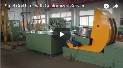
Coil upending and turning changes a heavy coil or pallet between the horizontal and vertical position without a crane and without manual effort. A tilting platform swings the load between the two positions in one controlled pass, and a clamping face on some machines also rotates the load about its vertical axis, so orientation changes are made safely in a confined cell. As a first-cut rule, a mechanical drive suits standard 90° moves on lighter loads, while a hydraulic drive suits heavy loads, 180° turns and a smooth cushioned pass. This guide explains the upender's place on a coil line, the mechanical and hydraulic build options, what to specify, and how to verify the machine before acceptance. It is written for plant engineers and purchasing managers who move coils or pallets between stations.
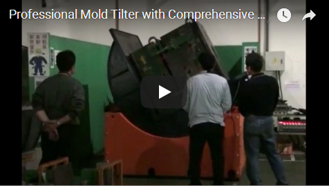
The video below shows a pallet inverter in the same coil-handling family, clamping and turning a palletized load in place:
Why Upend or Turn the Load at All
Coils leave a line in one orientation and arrive at the next process in another. A downlayer produces horizontal coils; the saw, press or packing station often needs them vertical, or vice-versa. The upender makes that change mechanically:
| Afhandelingstaak | Done without upender | Done with upender |
|---|---|---|
| Coil from horizontal to vertical | Sling, tag-line, two or more operators | One controlled platform pass; load stays clamped |
| Change orientation on the floor | Crane turn or man-handling | Platform or clamp rotation |
| Straighten / upset pallets | Manual levering, damage risk | Clamped, guided movement |
| Repeated daily cycles | Operator fatigue, dropped-load risk | Repeatable, same motion every cycle |
The safety win is consistency: the load follows a fixed travel path instead of swinging on a sling.
How an Upender Is Built: Mechanical vs Hydraulic Drive
The two common drive families differ in force and control:
| Aspect | Mechanische oplader | Hydraulische oplader |
|---|---|---|
| Drive | Electric motor with gear and screw/rack motion | Hydraulic cylinder or rotary actuator |
| Typisch capaciteitsbereik | About 1–60 t, per vendor line | About 1–100 t, per vendor line |
| Stroke control | Defined mechanical travel, stops | Variable-speed, cushioned pass |
| Best voor | Light coils, simple 90° use, lower budget | Heavy coils, 180° turning, long duty |
| Onderhoud | Less fluid system | Fluid system needs filter/level checks |
The capacity figures are the vendor's standard product-line ranges; the correct machine for any project is chosen from the load weight, coil size and floor layout, and confirmed per project.
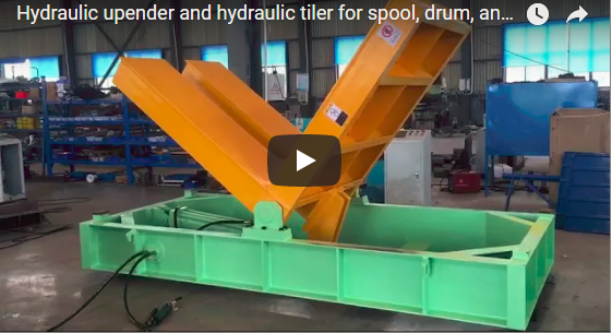
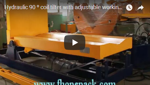
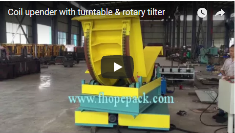
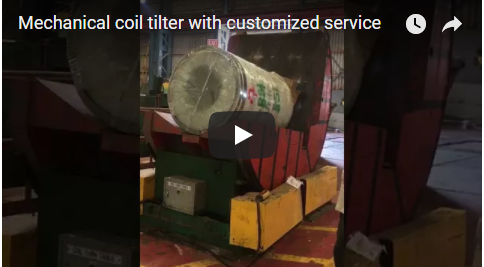
On the shown pallet-inverter geometry, an upper clamping frame holds the load while the platform turns it; a pivot or hydraulic drive swings the face through the turn. The exact build of any unit (fixed tilt, 180° turn, clamp rotation, conveyor integration) is a project decision, so state it to the manufacturer before quoting.
Wat te specificeren
Give the manufacturer the following per project:
| Invoer | Waarom dit zo belangrijk is |
|---|---|
| Belastingsgewicht en zwaartepunt | Sets the machine rating and whether an active clamp is needed. |
| Load size (width, depth, height) | Sets platform and clamp dimensions. |
| Orientation in and orientation out | 90° tilt, 180° turn, or clamp rotation. |
| Cyclustijd | Sets drive size and speed. |
| Integratie | Conveyor feed, pit depth, cell fencing, PLC hand-off. |
| Milieu | Indoors/outdoors, dust, wash-down, coil oil. |
| Safety perimeter | Light curtains, interlocked doors, two-hand controls. |
Fabriekstesten en acceptatie
Before dispatch, verify the testing record:
- Extended run. The vendor's stated practice on this family runs near-continuous testing before delivery (up to about 24 hours on hydraulic units). Verify this against the machine's own test log, not just the brochure.
- Control and safety. Confirm the control system was checked for smooth, responsive operation, and the emergency stop function verified, before delivery.
- Full-travel cycle. Evidence that the platform completed the full tilt/turn travel under a representative load without binding or sag.
- Clamp hold test (if applicable). Proof that the clamping face held the load through the turn without slip.
- Commissioning scope. A written definition of installation, commissioning and local on-site service.
- Coil Upender & Industrial Turnover Solutions – Official product page; mechanical ≈1–60T and hydraulic ≈1–100T options, EU-standard build, local on-site service.
- Hydraulic Upender & Handling Solutions – Official page; 24-hour pre-delivery test and control/safety verification practices.
- How 180° Turning Machines Work for Precast Components and Sheets – In-house kinematics reference with EN 415-10 / ISO 12100 safety notes.
On arrival: run an empty cycle, a loaded cycle, and verify the emergency stop before going into production.
FAQ
Q: Can one upender handle both 90° and 180° turns?
A: Yes, depending on build. A pivoting-face upender tilts through your range; a machine with clamp rotation also turns about the vertical axis. State both angles when specifying.
Q: What safety standards apply?
A: This machine family is designed with EN 415-10 as the machinery safety reference and an ISO 12100 risk assessment for the moving platform and clamp areas.
Q: Mechanical or hydraulic?
A: Mechanical suits lighter loads and simpler 90° moves and is simpler to maintain; hydraulic suits heavy loads and 180° turning with a cushioned pass. Both are valid; your weight and duty choose the drive.
Q: Do I need a pit?
A: Some upenders sit on the floor; low-profile or heavy units often recess into a shallow pit so the load line stays level. Give the manufacturer your floor height and conveyor height.
Q: How long does the cycle take?
A: Cycle time is a project variable driven by drive size and travel. Give the required throughput and the vendor sizes the drive and speed accordingly.
Volgende stap
Send the load weight and centre of gravity, load size, the in/out orientations, cycle time and integration needs (conveyor, pit, fencing, PLC), so the correct mechanical or hydraulic upender is sized on the approval drawing.