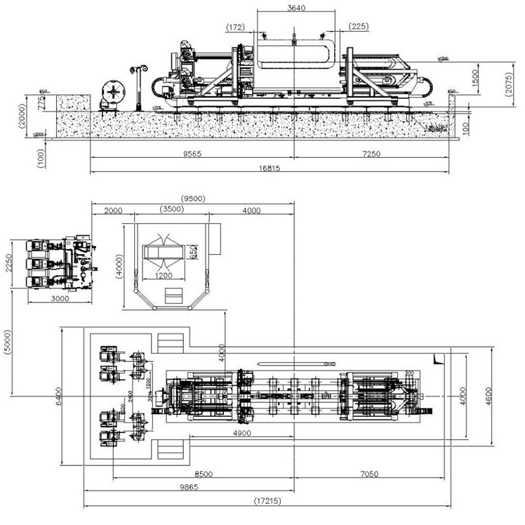
Santrauka: Black annealed wire coils loosen, telescope, or crush in transit when they are tied by hand. Manual spooling cannot hold uniform back-tension, manual twist knots relax under vibration, and untied voids collapse under stacking load. A single-station winder-binder closes all three gaps by metering wire length, winding on a collapsible mandrel, compacting the flanks, and tying the coil before ejection. The result is a repeatable coil envelope that downstream wrapping, weighing, and palletizing stations accept without rework.
Turinys
- Why Do Black Wire Coils Fail Before They Reach the Customer?
- What Happens From Pay-Off to Finished Coil in the Winding Sequence?
- How Do You Set Target Weight, OD, ID and Coil Build?
- Why Do Steel Wire Ties Beat Plastic Strap on Black Wire Coils?
- Why Four Ties in a Grid Pattern Hold a Coil Best?
- How Is Winding Tension Controlled to Keep the Coil Build Stable?
- What Technical Specifications Should a Black Wire Winder Meet?
- How Do You Match Winder Cycle Time to the Drawing Line Speed?
- What Does Workshop Integration Require in Layout, Power, Air and Safety?
- Which Acceptance Tests Prove a Coil Is Export-Ready?
- What Inputs Does an RFQ Need Before a Coil Winder Can Be Sized?
- Susiję pakavimo sprendimai
- Išvada
Why Do Black Wire Coils Fail Before They Reach the Customer?
Three failure modes dominate: axial telescoping, elastic tie relaxation, and inter-strand void collapse. All three are created on the drawing line, not during transport.
Black annealed wire pairs low yield strength, typically 300 to 450 MPa, with high elongation of 15% to 25%. That combination makes the wire easy to bend and hard to package: wound under manual tension, the turns store elastic energy that releases the moment the tie slackens.
- Axial telescoping. Hand winding cannot hold back-tension constant as the build radius grows. Forklift acceleration then pushes the unconstrained outer turns sideways along the coil axis.
- Tie relaxation. A hand twist knot is a friction joint. Road vibration creeps it loose, and a crane hook then lets the lower strands drape and tangle.
- Void collapse. Without positive compaction before tying, air stays trapped between wraps. Stacked three or four tiers in a container, the bottom coil ovalises.
Automation removes the operator variable: the same tension, compaction force and knot geometry repeat on every coil, and hands stay clear of whipping wire ends.
What Happens From Pay-Off to Finished Coil in the Winding Sequence?
The cycle runs five phases: straighten and meter, grip and wind, compact and cut, feed and twist the tie, collapse the mandrel and eject.
- Straightening and metering. Wire passes a dual-plane roll straightener that removes cast and helix. Twin metering wheels measure linear travel: the upper wheel carries a hardened ceramic or carbide surface to resist mill scale, the lower wheel a high-durometer polyurethane to avoid flat spots on soft annealed wire. An encoder closes the winding phase within ±10 mm of target length.
- Gripping and winding. A clamping jaw grips the wire end against a segmented steel mandrel. A vector drive accelerates the spindle on an S-curve while a servo ballscrew traverses the guide carriage across the face width, so turns lay parallel instead of crossing.
- Compaction and cut. At target length the spindle indexes to a stop, a snubber arm locks the tail, and a tool-steel shear cuts square. Two hydraulic flank rams then press the coil faces inward, driving loose turns into a dense rectangular section.
- Tie feeding and twisting. With the coil still under compaction, curved guide tracks pivot through clearance slots in the mandrel segments. A motorised feed drives the tie wire around the bundle; the head tensions it, twists a pigtail knot, and cuts flush. For four-tie recipes a servo table indexes the coil 90 degrees between ties.
- Collapse and ejection. Hydraulic draw-bars pull toggle links so the mandrel segments retract radially by 30 to 45 mm, breaking the residual grip. A pusher plate transfers the self-supporting coil to a roll bed or turnstile.
How Do You Set Target Weight, OD, ID and Coil Build?
Coil geometry follows from wire gauge, steel density, mandrel diameter, face width, and build height. Every recipe should be calculated, not guessed.
Carbon steel wire has a nominal density of 7.85 g/cm³, that is 7,850 kg/m³. For a round strand of diameter d:
A_wire = pi * (d / 2)²
m_line = A_wire * rho_steel
For 2.0 mm black annealed wire:
A_wire = 3.14159 * (0.002 m / 2)² = 3.14159e-6 m²
m_line = 3.14159e-6 m² * 7850 kg/m³ = 0.02466 kg/m
A 50 kg export bundle therefore needs:
L_wire = 50 kg / 0.02466 kg/m = 2027.57 mWith an inner diameter of 300 mm and an outer diameter of 500 mm, the mean turn is:
D_mean = (0.50 m + 0.30 m) / 2 = 0.40 m
C_mean = 3.14159 * 0.40 m = 1.2566 m
N_turns = 2027.57 m / 1.2566 m = 1613.5 turns
Two design rules follow. First, the mandrel collapse stroke must exceed elastic springback plus thermal contraction:
Delta_D >= D_expanded - D_collapsed minimum 25 mm, typically 30-45 mmSecond, for rectangular or irregular bundles the envelope is the circumscribed circle, not the width:
OD_env = sqrt(W² + H²)Worked example, example only: a 400 mm by 300 mm bundle gives OD_env = sqrt(160000 + 90000) = 500 mm, so it needs the same mandrel class as a 500 mm round coil.
Why Do Steel Wire Ties Beat Plastic Strap on Black Wire Coils?
This machine ties with steel wire, twisted into a pigtail knot. The tie is the same material as the coil, so it survives a second anneal, melts with the coil at the smelter, and needs no consumable sorting on the mill floor. Plastic strap only wins where surface marking on bright wire is the reject criterion, and that is a different platform.
                 BINDING MEDIA DECISION PATHWAY
                              |
        Does the coil pass through a second anneal?
                              |
                    +---------+---------+
                    |                   |
                   YES                  NO
                    |                   |
           Steel wire tie      Is surface marking
           (no melting risk)   a reject criterion?
                              +---------+---------+
                              |                   |
                             YES                  NO
                              |                   |
                     PP / PET strap        Steel wire tie
(friction weld) (lowest cost)- Steel wire tie. 1.2 to 1.6 mm annealed binding wire from a payout carrier, closed by a planetary twisting head into a 3.5 to 4.5 turn pigtail. Joint strength reaches roughly 90% to 95% of the tie wire’s own breaking load, and the tie melts with the coil at the customer’s furnace.
- PP arba PET juosta. 9 to 12 mm wide and 0.4 to 1.0 mm thick, closed by friction-vibration weld and tensioned between 100 and 1000 N. The flat profile spreads retention force and avoids scoring soft wire, but the strap is a second material in the scrap stream and does not survive re-annealing.
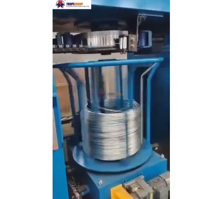
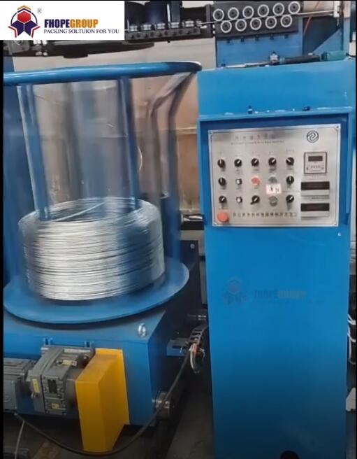
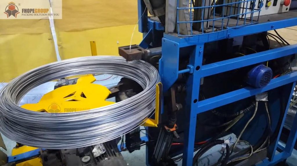
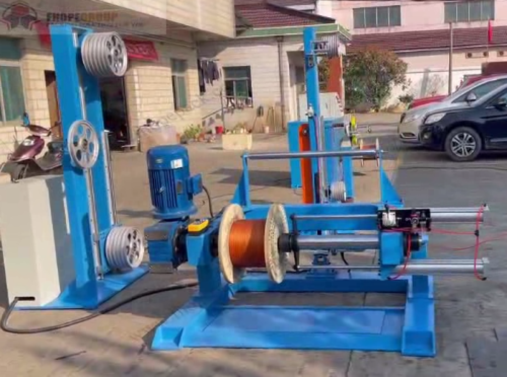
Platform separation matters. The compact single-head unit shown above is a wire-tie machine, and that is the configuration specified for black annealed wire. If the mill needs plastic strapping on bright wire, the horizontal FPCL-W500 automatic steel wire winding and strapping unit is the matching platform. For flexible cable and cord sets, the cable winding and binding machine runs on entirely different length and tension boundaries.
Why Four Ties in a Grid Pattern Hold a Coil Best?
Four ties, two in each direction, crossing into a grid: each pair clamps two opposite faces of the coil, and the crossing points lock the pack against both axial spread and ovalisation. Four ties in a grid is the standard configuration on this machine; two ties remain available as a light-duty recipe.
Tie tension must be even, or the coil turns into a polygon the moment the mandrel releases.
- Grid array, four ties. Two ties run one way, two run perpendicular, forming a grid over the coil faces. The spindle indexes 90 degrees between pairs, so the second pair crosses the first. This is the export configuration: it resists axial spread, stops the coil shearing into an oval, and keeps the pack square for crane handling.
- Two-tie recipe. For light domestic coils or bundles stacked flat on pallets, two ties at 180 degrees are enough. The same head runs the shorter recipe without a mechanical change.
Heavy coils move to line equipment. The vielos ritės suspaudimo ir surišimo pakavimo linija handles GI coils of 800 to 1300 mm OD and 450 to 600 mm ID, 2.5 to 8.0 mm wire, up to 2,000 kg, with 2 to 3 t of compaction and four straps per coil.
How Is Winding Tension Controlled to Keep the Coil Build Stable?
Tension must be closed-loop, not fixed. As the build radius grows, shaft torque has to rise in proportion, or the outer layers crush the inner ones.
A dancer arm between the drawing block and the winder absorbs speed transients. Proportional valves hold cylinder backpressure at 0.3 to 0.7 MPa; a potentiometer reports arm angle to the PLC, which trims servo speed.
Torque scaling with radius:
T_motor(t) = F_tension * r(t) / (i_gearbox * eta_mech)Target back-tension is normally held at 10% to 18% of the wire yield load. Traverse gearing follows spindle speed:
v_traverse = k_pitch * d_wire * n_mandrelThe overlap ratio k_pitch is typically 1.02 to 1.08. Below 1.0 the turns climb over each other; far above it the pack develops valleys. A one-way bearing on the infeed prevents back-feeding when the shear fires.
What Technical Specifications Should a Black Wire Winder Meet?
Presumed tiers for a single-station winder-binder follow. They are engineering estimates, not catalogued models; confirm every value on a final arrangement drawing before order.
| Parametras | Tier L (fine wire) | Tier M (commercial) | Tier H (heavy) |
|---|---|---|---|
| Max envelope OD, circumscribed | 400 mm | 600 mm | 800 mm |
| Ritės ID diapazonas | 150 iki 220 mm | 250 iki 350 mm | 350 iki 500 mm |
| Vielos skersmuo | 0.5 iki 2.0 mm | 1.6 iki 4.5 mm | 3.0 iki 6.5 mm |
| Ritės svoris | 5 - 30 kg | 20 - 60 kg | 50 - 120 kg |
| Suklio greitis | iki 1200 aps./min | iki 800 aps./min | iki 450 aps./min |
| Linear winding speed | iki 800 m/min | iki 600 m/min | iki 400 m/min |
| Binding media | 1.0 to 1.2 mm steel wire | 1.2 to 1.6 mm steel wire | 1.6 to 2.0 mm steel wire |
| Kaklaraiščio raštas | 2-tie recipe | 4 ties, grid | 4 ties, grid |
| Mandrel collapse stroke | 25 mm | 35 mm | 45 mm |
| Pagrindinis veleno variklis | 7.5 kW | 15 kW | 22 kW |
| Hidraulinis slėgis | 10 Mpa | 14 Mpa | 16 Mpa |
| Pneumatinis tiekimas | 0.6 MPa dry air | 0.6 MPa dry air | 0.6 MPa dry air |
Presumed envelope for the compact unit: 0.7 to 4.0 mm wire, 200 to 350 mm ID, 350 to 600 mm OD, 150 to 200 mm face width, 25, 50 or 100 kg recipes, up to 900 m/min winding speed, four wire ties in a grid as the standard pattern, and noise below 78 dB(A) at 1 m. All of it is to be confirmed with the manufacturer.
How Do You Match Winder Cycle Time to the Drawing Line Speed?
Cycle time is winding plus dead time. When winding plus dead time exceeds the drawing rate, the accumulator empties and the line stops.
Worked case: 2.0 mm wire at 10.0 m/s, which is 600 m/min, in 50 kg coils on a Tier M unit.
Net winding = 2027.57 m / 10.0 m/s = 202.76 s
Dead time   = 4.0 s decel + 3.0 s cut and compact + 20.0 s for four ties + 10.0 s collapse and eject = 37.0 s
Cycle       = 202.76 + 37.0 = 239.76 s  ->  15.02 coils/h  ->  751 kg/h
Two levers exist. A twin-mandrel turret hides the 37 s dead time behind the next winding cycle, taking output toward the winding limit of about 17.8 coils/h. Or raise coil weight: at 100 kg the same dead time costs half as much per kilogram. Published rates of up to 60 coils per hour belong to light coils on dual-spindle machines where tying overlaps winding; they do not transfer to 50 kg single-mandrel output.
What Does Workshop Integration Require in Layout, Power, Air and Safety?
Three things decide whether the winder runs or stalls: air volume at the compaction stroke, a dedicated three-phase feed, and a safety chain interlocked with the drawing block.
+------------------------------------------------------------------------+
|                     WORKSHOP INTEGRATION LAYOUT                        |
|                                                                        |
|  [ DRAWING BLOCK ] --> [ ACCUMULATOR ] --> [ DANCER TENSION UNIT ]     |
|                                                    |                   |
|                                                    v                   |
|  [ RUNOUT BED ] <-- [ BINDING HEAD ] <-- [ WINDING MANDREL ]           |
|         |                                                              |
|         v                                                              |
|  [ DOWNSTREAM WRAPPER OR PALLETIZING BAY ]                             |
+------------------------------------------------------------------------+- Oro. Mandrel expansion, compaction and the shear fire within seconds. Fit a 100 litre buffer tank within 3 m of the machine; a shared ring main drops pressure exactly when compaction needs it.
- Galia. A dedicated fused disconnect for the servo drive, sized for regenerative spikes during emergency stops, with line filters and an earthed cabinet per EN 60204-1.
- Maketas. Keep crane and forklift access to the discharge face. Align the infeed centre line with the existing take-up frame height and anchor the frame to a reinforced slab, so drum harmonics do not migrate into the building.
- Safety chain. Enclosed wire tunnels, interlocked perimeter fencing, and light curtains across the ejection portal, designed to EN ISO 12100 risk assessment, ISO 13849-1 Category 3 architecture, ISO 4414 for the pneumatic circuit, and EN 61496-1 for the light curtain. An E-stop must brake the spindle to a dead stop and interlock upstream with the drawing block.
Which Acceptance Tests Prove a Coil Is Export-Ready?
Run the factory acceptance test at full speed, not demo speed. Five measurements decide acceptance: weight spread, ID repeatability, OD concentricity, knot integrity, and stop time.
| Atrask | Priėmimo kriterijus |
|---|---|
| Svorio pastovumas | 10 consecutive coils within ±1.0% of recipe |
| ID repeatability | mandrel expands and collapses cleanly, ID within ±2.0 mm |
| OD concentricity | OD variance under 5.0 mm across the face |
| Traverse quality | level pack, no crossing turns or pinch-downs |
| Knot integrity | 3 to 4 clean turns, no split or bird-caged ends |
| Kaklaraiščio raštas | four ties present, grid crossings square, ties seated on both flanks |
| Tie tension | coil lifts on a crane C-hook without tie creep |
| Uodegos ilgis | flush cut, tail within recipe limit |
| E-stop braking | spindle stops from maximum speed without unspooling |
| Triukšmas | below 78 dB(A) at 1 m |
What Inputs Does an RFQ Need Before a Coil Winder Can Be Sized?
Missing inputs are the main cause of oversized frames and undersized drives. Six data blocks close the specification.
| Indėlis | Kodėl tai reikalinga | Jei trūksta |
|---|---|---|
| Wire diameter min and max | sets metering wheels, traverse pitch, shear | drive and shear sized by guess |
| Tensile and surface condition | sets tension target and wheel hardness | tension too high, wire marked |
| Coil ID, OD and face width | sets mandrel segments and stroke | coil will not release cleanly |
| Target coil weight | sets length recipe and cycle time | throughput cannot be quoted |
| Linijos piešimo greitis | sets accumulator and turret decision | line stops at every coil change |
| Binding medium and tie count | sets binding head and index table | wrong consumable path |
Send the six blocks with a plant layout; our engineers return a technical concept within 24 hours and a GA drawing within 48 hours.
Susiję pakavimo sprendimai
Downstream and adjacent equipment:
- FPCL-W500 automatic steel wire winding and strapping unit — horizontal PP-strap platform for bright wire, where plastic strap replaces wire ties.
- Industrial wire coil wrapping machines — eye-through stretch wrapping for rust protection.
- Wire coil compressing and strapping packing line — heavy coils to 2,000 kg with 2 to 3 t compaction.
- Complete wire packaging systems — turnkey coil handling, weighing, and stacking.
- Cable winding and binding systems — benchtop winders for cable and cord sets.
- Industrial coil packing machinery — radial wrappers for steel, copper, and wire coils.
- Horizontal stretch wrapping solutions — bundling for long products.
Išvada
Match the machine to the coil, not the coil to the machine. A single-mandrel winder-binder running four wire ties in a grid covers black annealed coils from 25 to 100 kg at drawing speeds below 10 m/s. Above 50 kg with a line speed over 12 m/s, add a twin-mandrel turret so the 37 s tie and eject sequence hides behind the next coil. Above 2,000 kg, only a line will hold the cycle.
Submit wire gauge, coil weight target, and layout to www.fhopepack.com for a concept within 24 hours and a GA drawing within 48 hours.