Top Solutions for Minimizing Springback in Steel Coils
Are you struggling with the persistent challenge of springback in steel forming operations? This elastic recovery after bending is a major headache, causing dimensional inaccuracies, increased scrap, and costly rework. Tired of chasing tolerances and battling unpredictable part shapes? It’s time to master the techniques that minimize this frustrating phenomenon.
Minimizing springback in steel coils during forming and handling is critical for achieving dimensional accuracy, ensuring safety, and optimizing processes. Key solutions involve strategically modifying the forming process and tooling, managing material properties, and employing proper handling and packaging techniques. This includes techniques like post-stretching, over-forming, reducing elastic stresses through process design, locking stresses with geometric features, optimizing tooling parameters, and securing coils with appropriate strapping. Implementing these methods reduces costly rework and improves manufacturing efficiency.
Understanding the fundamental principles behind springback and implementing proven mitigation strategies can dramatically improve your results. Read on to explore the top technical approaches and best practices used in the industry to tackle springback head-on and achieve consistent, accurate parts.
Understanding and Addressing Springback in Forming
Springback, the elastic recovery of material after forming, is a primary challenge in sheet metal operations, particularly with high-strength steels. Parts formed at room temperature inherently develop elastic stresses; when the forming load is removed, these stresses are released, causing the part to deviate from the desired shape. Addressing this requires techniques to manage or eliminate these stresses.
Springback in steel coil forming stems from the elastic stresses induced during deformation. When the tooling load is released, the material attempts to return to its original, flat state. This elastic recovery manifests as angular change (deviations in bend angles) and sidewall curl (distortion in upright walls). The magnitude of springback is influenced by material properties like yield strength and thickness, as well as process parameters such as bend radius, die clearance, and forming temperature. High-strength steels, with their higher yield strength and elastic modulus, exhibit more significant springback, necessitating advanced mitigation strategies like post-stretching, over-forming, or modifying tooling and part geometry to achieve desired dimensional accuracy. Forming at elevated temperatures, like in press hardening, allows for stress relief before unloading, significantly reducing springback.

The Root Cause: Elastic Stress Release
When sheet metal is bent, the outer fibers are put into tension, while the inner fibers are put into compression. Ideally, there’s a neutral axis within the material thickness experiencing zero stress. During bending, the stresses exceed the material’s yield strength, causing plastic deformation, but elastic stresses remain. When the load is removed, the elastic tensile stresses attempt to shrink the outer layers, and the elastic compressive stresses attempt to elongate the inner layers. This differential stress distribution through the thickness drives springback. The larger the difference in elastic stress between the tension and compression zones (∆σ), the greater the springback. This effect is amplified in areas where the material undergoes severe bending and unbending, such as when flowing through draw beads and over die radii, leading to sidewall curl. Work hardening of the material during the forming process further increases the yield strength, magnifying the magnitude of elastic stress and, consequently, the springback. Minimizing bend/unbend cycles and reducing strain levels can help manage the initial elastic stress levels.
Key Approaches to Correction
Springback correction methods primarily fall into three categories:
- Changing the Elastic Stress Distribution: Modifying the stress state within the material after forming to reduce the detrimental tensile-to-compressive gradient.
- Reducing or Minimizing the Elastic Stresses: Altering the forming process or tooling design to create lower levels of elastic stress during deformation.
- Locking in the Elastic Stresses: Incorporating geometric features into the part design that resist the release of elastic energy, effectively holding the desired shape.
Implementing compensation in the initial forming stages is generally more effective and cost-efficient than attempting correction in subsequent operations.
Changing Elastic Stress Distribution
A powerful approach to counter springback is to alter the distribution of elastic stresses within the formed part before it leaves the die. Instead of allowing the inherent tensile-compressive gradient to cause distortion, techniques are applied to make the through-thickness stress state more uniform or shift it towards a less damaging all-tensile state.
Modifying the elastic stress distribution minimizes springback by altering the internal stress balance. Post-stretch techniques apply an in-plane tensile force to transform harmful tensile-compressive elastic stress gradients into a more uniform all-tensile state, significantly reducing angular change and sidewall curl. Over-forming involves intentionally over-bending the part; upon elastic recovery, it settles into the desired dimension. Rotary bending offers easy angle adjustment, while specific flange wipe die designs with back relief can induce compressive stresses at the bend radius, promoting plastic deformation and reducing elastic recovery.

Post-Stretch Techniques
Post-stretching involves applying a controlled tensile strain to the formed part while it is still in the die. This operation is typically performed after the primary bending and drawing sequences. The objective is to apply sufficient in-plane tensile force to the sidewall area to induce a minimum tensile strain (often targeted at around 2%). This tensile strain overrides the localized compressive elastic stresses, converting the through-thickness stress gradient to a predominantly or entirely tensile elastic stress state. With both sides of the bend now exhibiting tensile elastic stresses, the tendency for angular change driven by the differential stress (∆σ) is significantly reduced, ideally approaching zero. Instead of bending outwards, the wall simply shortens slightly, which can be accommodated by punch stroke adjustment.
Several die design methods facilitate post-stretching:
-
Stake Beads: These features, located on the blankholder or punch, engage late in the press stroke to grip the flange and restrict material flow, forcing a stretch in the sidewall as the punch continues its travel. Retractable stake beads offer flexibility during tryout, while punch-mounted beads may allow for smaller blank sizes. However, stake beads require significant press force and energy, especially with work-hardened AHSS, and improper design can lead to fracture. Careful consideration of stake bead geometry and location relative to punch openings is critical. Combining draw beads and stake beads can help promote a more uniform stress distribution.
-
Hybrid Beads: A variation of stake beads, hybrid beads use stinger features to penetrate the sheet and create a wave form. They require less surface area than conventional stake beads, reducing blank size and required tonnage. They also minimize bending over tight radii, reducing splitting risk.
-
Active Binder Force Control: Modern presses with multipoint-control cushions allow for dynamic adjustment of blank holder force during the stroke. Increasing the blank holder force significantly at the end of the stroke can restrict material flow and induce the desired post-stretch in the sidewall. Varying the pressure profile throughout the stroke can further optimize metal flow and springback control.
Post-stretch operations are highly effective, particularly for reducing sidewall curl and angular change in challenging AHSS components. However, the increased forces involved necessitate robust tooling and sufficient press capacity.
Over-Forming Methods
Over-forming, also known as over-bending, is a strategy where the tool geometry is designed to bend the part beyond its nominal angle. The material then springs back to the desired angle upon load removal. This technique is particularly effective for correcting angular change.
Rotary bending tooling is often preferred over flange wipe dies for over-bending due to its ease of angle adjustment, which simplifies compensating for variations in material properties, lubrication, or press settings. It also avoids the tensile loading inherent in wiping operations.
If flange wipe dies are used for over-bending, specific die designs are necessary. This includes using a die radius smaller than the desired part radius and incorporating back relief on both the die and the punch. This configuration intentionally subjects the bend radius to compressive stresses between the punch and die at the bottom of the stroke. This squeezing action, along with associated thinning at the radius, promotes plastic deformation, leaving minimal elastic recovery.
The effectiveness of over-forming is heavily influenced by part geometry, particularly cross-sectional design. Certain designs, like simple 90-degree channels, may be difficult to over-bend effectively and are prone to severe sidewall curl, especially with AHSS. Redesigning cross-sections to allow for easier over-bending and incorporating gradual transitions and larger radii (where formability permits) can significantly mitigate springback and distortion.
Multi-stage forming is another technique that can incorporate over-bending. Complex part shapes, like hat sections with right angles, can be formed in multiple steps. Initial stages might involve over-bending 90-degree features using "gull-wing" processes, with subsequent stages flattening larger radii or coining small features, potentially incorporating further over-bending or coining to finalize dimensions and control springback.
Comparing Cross-Section Designs for Springback (Based on provided text):
| Feature/Design Aspect | Sketch A (Less Favorable) | Sketch B (More Favorable) | Impact on Springback |
|---|---|---|---|
| Rail Cross Section Design | Vertical draw walls, sharp inner corner | Angled walls, larger blending radius | Sketch B allows easier over-bending, reduces curl |
| Closed Box Section (Welded) | Two sections with 90-degree corners (Hat) | Hexagonal section | Hexagonal reduces curl/twist, permits over-bend |
| Radii Transitions | Sharp, potentially stress risers | Gradual transitions | Gradual transitions minimize stress risers/distortions |
| Sidewall Curl in Channels | Likely severe | Reduced | Design influences susceptibility to curl |
| Angular Change Compensation | Difficult to over-bend | Allows for over-bending | Design enables effective over-bending compensation |
| Impact Shock Load (Draw Punch) | Higher | Reduced | Angled walls cushion impact |
| Required Binder Pressure/Forces | Higher | Lower (once formed) | Vertical walls need more control |
Minimum bending radii requirements increase significantly with increasing steel strength and bend radius. For AHSS grades above 590 MPa, inside product radii should be at least 3T, and die radii over which material is pulled under tension should be at least 5T to manage formability and springback. Careful selection of material grade in conjunction with appropriate die radii is essential.
Reducing and Locking In Elastic Stresses
Beyond actively changing the stress state, strategies also focus on minimizing the magnitude of elastic stresses created during forming or preventing their release after formation. Modifying the process flow and tooling can reduce the inherent elastic energy stored in the material, while clever part design can create features that act as internal stiffeners, resisting the tendency to spring back.
Reducing springback can be achieved by minimizing the elastic stresses generated during the forming process. This involves optimizing process design and tooling to avoid excessive bending/unbending, control metal flow, and manage strain distribution. Alternatively, springback can be controlled by locking existing elastic stresses within the part through the use of geometric stiffeners like darts, beads, or flanges. These features resist the elastic recovery forces, maintaining the desired shape, though subsequent operations may inadvertently release these trapped stresses.
Process and Tooling Optimization
The way a part is formed has a direct impact on the level of elastic stresses generated. Process designers can choose or modify forming methods to reduce the amount of elastic energy stored. For example, comparing different methods for forming a hat-profile channel reveals significant differences in resulting springback:
- Draw: Conventional deep drawing involves continuous blankholder force and significant bending/unbending over die radii, leading to maximum sidewall curl.
- Form-Draw: Blank holder force is applied late in the stroke. This minimizes bend-unbend deformation early on and allows for high tensile stress at the end, achieving a post-stretch effect and effectively reducing sidewall curl.
- Form: Flange is formed late. Limited bend-unbend. May lead to wrinkles without blankholder control.
- Bend: Simple bending process avoids bend/unbend sequence in the wall, reducing sidewall curl but may lead to angular change.
Minimizing bending and unbending as the metal flows into the part shape reduces distortion and tool wear. Reaching minimum strain levels across the panel also helps minimize springback and sidewall curl. Tooling considerations are also key: ensuring sufficient tool stiffness, keeping die clearance as tight as formability allows (to restrict unwanted bending/unbending), and designing punch radii as sharp as permissible (while respecting material bendability limits, especially for AHSS, to minimize angular change). Uniform depth in channel parts and gradual shape transitions help avoid forming distortions, particularly in areas prone to compression.
Comparison of Forming Processes for Hat-Profile Channel (Based on provided text Figure 17):
| Process | Description | Primary Effect on Springback | Sidewall Curl | Angular Change | Notes |
|---|---|---|---|---|---|
| Draw | Conventional, continuous blankholder, max bend/unbend over die radius | Creates maximum elastic stress | Maximum | Significant | Standard method, high springback risk |
| Form-Draw | Blankholder force applied mid-to-late stroke | Minimizes initial bend/unbend, enables late post-stretch | Minimized | Reduced | Effective for curl, requires control |
| Form | Flange created late, slight bend/unbend | Lower elastic stress | Reduced | Moderate | Risk of wrinkles without blankholder |
| Bend | Simple bending, avoids bend/unbend sequence | Minimizes curl-inducing stresses | Minimized | Potentially high | May introduce significant angular change |
This table highlights how process choice fundamentally influences the elastic stress state and subsequent springback behavior.
Using Geometric Stiffeners
A part’s geometry can be designed to inherently resist the release of elastic stresses. Adding features like darts, beads, ribs, or strategically placed flanges can act as stiffeners, locking in the elastic energy and maintaining the desired shape. These features increase the part’s rigidity and resistance to deformation, effectively countering the springback forces.
Examples include incorporating vertical beads into the sidewalls of channel or hat sections to equalize the length of line and minimize twist, or using darts and step flanges on drawn walls. These features work by increasing the moment of inertia in the area where elastic stresses are concentrated, making it harder for the part to spring back.
While effective, adding these features in a restrike operation can be challenging, especially with AHSS, because the material’s yield strength increases significantly after work hardening. The tooling must be robust enough and the press must have sufficient force and energy to form these stiffening features in the work-hardened material. Furthermore, while these features lock in stresses, subsequent manufacturing steps such as trimming, punching, or even heating can potentially unbalance the residual stress distribution, leading to unexpected dimensional distortions. Therefore, the entire process chain should ideally be considered and simulated when using this approach.
Advanced Techniques and Material Considerations
Pushing the boundaries of springback control involves innovative forming processes and leveraging the consistency and properties of advanced materials. Simulation plays a crucial role in predicting behavior and validating mitigation strategies before committing to physical tooling.
Advanced techniques for minimizing springback in steel coils include innovative processes like Compressive Stress Superposition (Smartform) which balances stresses internally through compression. Material properties, particularly consistency in yield strength, thickness, and bendability, significantly impact springback predictability. Steels designed for consistent bending performance reduce variation. Simulation tools are essential for predicting springback behavior, testing countermeasures, and optimizing processes, but physical verification remains crucial for final validation.
The Compressive Stress Superposition process, commercially known as Smartform, is a patented technique designed specifically to address springback by balancing internal stresses. It utilizes a two-step forming process: a preform stage (OP20) followed by a sizing/calibration stage (OP30). In the preform stage, the material is formed into a general shape without significant drawing, allowing for flexible tool design (e.g., enlarged radii to prevent cracks/wrinkles). The critical second stage involves sizing the part by compressing the material rather than drawing it. This compressive action creates a more uniform stress distribution through the thickness compared to conventional bending or drawing. This process has been shown to be less sensitive to variations in sheet metal properties, leading to a more robust manufacturing process and effective springback control for high-strength steels (590 MPa through 1180 MPa). Another benefit is material savings, as the starting blank size can be closer to the final part geometry due to reduced drawing.
Material properties are inherently linked to springback. Steels with higher yield strength store more elastic energy, leading to greater springback. Consistent material properties are paramount for predictable springback. Steels like SSAB’s Strenx® and Hardox® are manufactured with tight tolerances for thickness, flatness, and guaranteed bending properties across multiple bend classes. This consistency allows manufacturers to rely on predictable springback behavior, enabling repeatable forming results on standard equipment and simplifying springback compensation. The difference between U-die and V-die bending, top punch radius selection, and the influence of rolling direction are also critical considerations when bending special steels. Tools like SSAB’s BendCalc app can instantly calculate bending parameters, including predicted springback, based on steel characteristics and tooling setup.
Simulation software has become an indispensable tool in modern metal forming. Its accuracy in predicting springback continues to improve, especially with detailed material characterization data. While simulations may not always be perfectly accurate, they are invaluable for predicting trends, comparing the effectiveness of different tooling or process modifications, and guiding initial compensation strategies. However, predictions must always be validated against physical measurements from die tryouts.
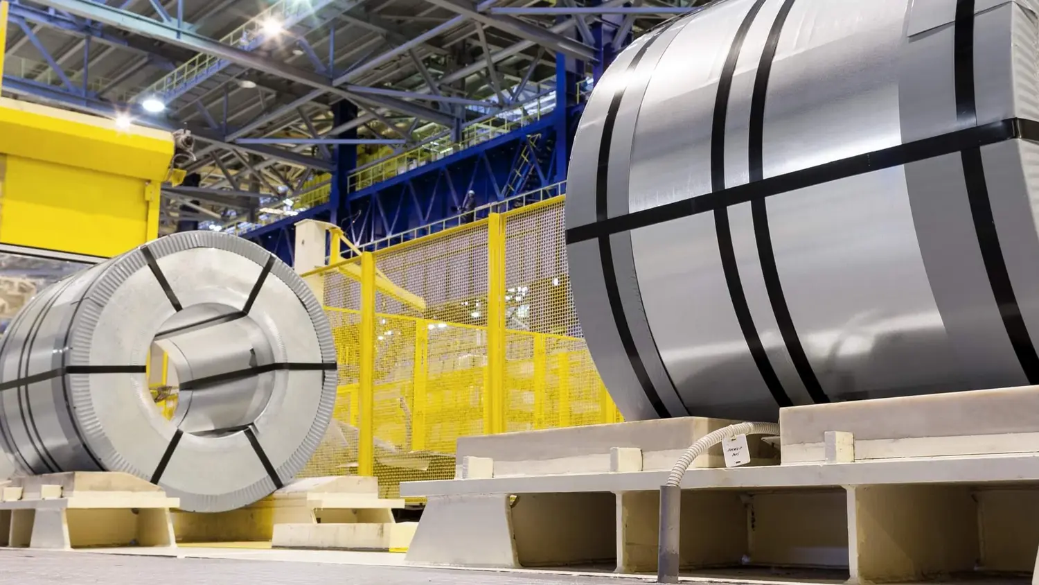
Preventing Coil Unwinding Springback in Handling and Storage
Springback isn’t limited to the forming press; it’s also a critical safety and material integrity issue during the handling, storage, and transportation of coiled steel materials. Uncontrolled release of the significant elastic energy stored in a coil can cause it to unwind rapidly and dangerously.
Preventing dangerous springback in steel coils during handling involves rigorous strapping and packaging protocols. This includes selecting high-tensile banding with appropriate strength and finish for the material and environment, applying consistent tension using reliable tools (manual or automated), and securing joints effectively. Crucially, proper coil preparation (tail position), safe handling procedures, using edge protection, and robust palletizing or skidding minimize movement and maintain banding integrity, ensuring workplace safety.

The Risks and Contributing Factors
Coiled steel, particularly higher-strength grades, stores substantial elastic energy, much like a compressed spring. If the restraints (strapping, packaging) are insufficient or fail, this energy can release violently, causing the coil to unwind rapidly. This poses severe safety risks to personnel in the vicinity (cuts, impacts from flying material or whipping bands) and can cause significant damage to the material itself (kinks, scratches, unusable length).
Several factors contribute to the likelihood and severity of this unwinding springback:
| Factor | Impact on Springback (Unwinding) | Mitigation Strategy |
|---|---|---|
| Material Yield Strength | Higher yield strength = More stored energy | Use higher tensile strength banding, increase number of bands |
| Material Thickness and Width | Thicker/Wider = More force | Use wider, stronger banding; reinforced packaging |
| Coil Diameter | Smaller diameter = Greater internal stress | Increase circumferential banding; secure the coil bore |
| Surface Coatings | Can affect friction/elastic properties | Consider coating during banding selection and tensioning |
| Manufacturing Processes | Cold working/rewinding induces stress | Exercise extra caution during handling; enhance packaging |
| Insufficient Banding | Restraint fails | Ensure adequate number, placement, and tension of bands; proper banding material |
| Damaged Packaging/Banding | Restraint compromised | Regular inspection; immediate replacement of damaged materials; edge protection |
| Improper Handling/Storage | Coil movement, dropping, poor stacking | Strict adherence to safe handling protocols; stable, chocked storage |
Understanding these factors allows for tailored securement strategies.
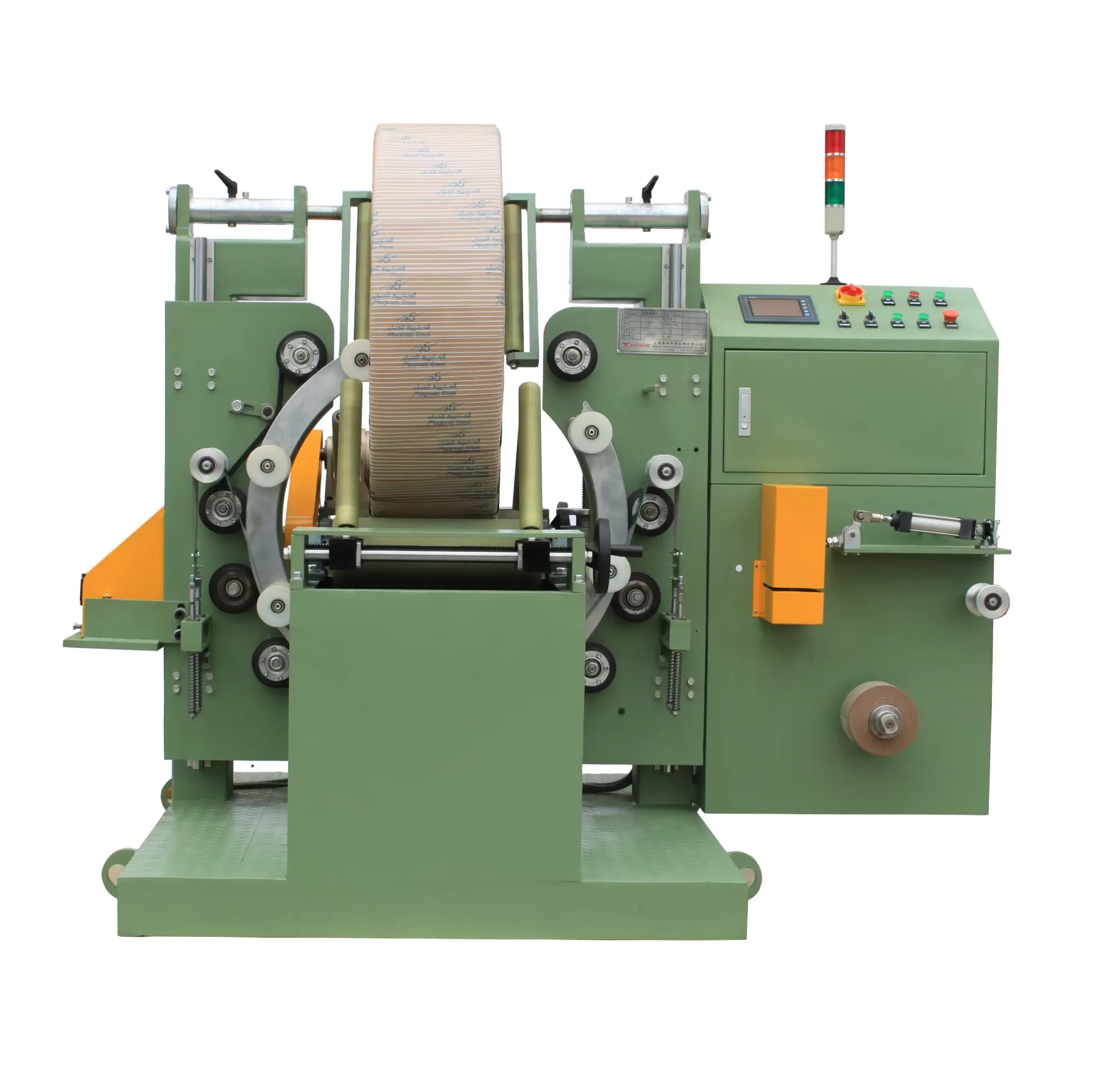
Strapping and Packaging Solutions
Effective prevention relies on a combination of appropriate materials, tools, techniques, and safety protocols. Steel banding is the standard due to its high tensile strength and low elongation, crucial for resisting the outward forces of the coil. High-tensile steel banding is recommended for heavy or high-strength coils. The banding material’s finish (plain, painted, galvanized) should suit the storage environment to prevent degradation.
Tools like manual tensioners and sealers, or more advanced automated banding systems, are used to apply consistent tension (typically 30-50% of break strength) and secure the band ends with reliable joints (crimped, seal-less, welded). Automated systems offer significant advantages in high-volume operations, providing consistency and speed.
Beyond strapping, optimizing the overall packaging provides crucial secondary containment. This includes wrapping the coil with robust materials like stretch film or reinforced paper, especially for moisture protection and containment. Edge protectors (cardboard, plastic, metal) placed under the banding prevent the bands from cutting into the coil edges and distribute pressure evenly, protecting both the coil and the banding integrity. Securing coils to pallets or skids with banding or wrapping, and using chocks or bracing, prevents shifting during transport and storage. Finally, clear springback warning labels and handling instructions on the packaging are essential safety measures.
Conclusion
Minimizing springback in steel coils is a multifaceted challenge that requires a deep understanding of material behavior and diligent application of proven techniques throughout the manufacturing and handling processes. By implementing advanced forming strategies like post-stretching and over-forming, optimizing tooling and process design to reduce elastic stresses, leveraging geometric features to lock in shape, and utilizing advanced materials and simulation, manufacturers can significantly improve dimensional accuracy and reduce costly rework. Furthermore, rigorous strapping and packaging protocols, utilizing appropriate materials and tools, are critical for preventing dangerous springback during coil handling and storage, ensuring both safety and product integrity. Mastering these solutions is key to achieving higher efficiency and consistent quality in metal processing operations, often facilitated by advanced steel coils handling and packaging solutions.


