The 90% Efficiency Rule: Your Step-by-Step Guide to Coil Packing Line Design
Summary: A coil packing line is a synchronized system of machines that protects and prepares metal coils for shipment. The right layout can boost throughput by over 90%, while a poor design creates constant bottlenecks and damage.
Phase 1: The Foundation – Auditing Your Reality
You’re planning a new line. The pressure is on. The sales team promised faster delivery, but the current process is a patchwork of manual lifts and temporary staging areas. Coils get scratched, forklifts are constantly in the way, and your team spends more time moving coils than packing them. The first bottleneck isn’t the machine—it’s the plan.
A successful layout starts not with equipment brochures, but with a deep audit of your own shop floor data and constraints. You must translate your production goals into physical, measurable requirements for space, flow, and machine performance.
🛠️ Step 1: Measure Your Inputs & Outputs
Your coil data dictates everything. Guessing here will haunt you for years.
- Coil Dimensions & Weight: Record the full range—minimum to maximum OD, ID, width, and weight. Don’t just plan for the average.
- Production Rhythm: Calculate your required throughput in TPH (Tons Per Hour). Is it 20 TPH or 100 TPH? This number defines your machine cycle times.
- End Destination: How will the packed coil leave? By sideloader truck, overhead crane, or forklift? This determines your exit lane design and door height.
ROI Insight: Underestimating coil weight variance by just 10% can force a costly upstream slowdown, crippling the ROI of your entire automation investment. Over-spec from the start.
🛡️ Step 2: Conduct a Spatial Forensics Study
Walk your floor with a tape measure and a critical eye.
- Footprint Mapping: Measure the actual available length, width, and clear height. Account for columns, overhead pipes, and maintenance aisles. A 3D model is ideal here.
- Material Ingress/Egress Points: Map the distance from the mill/slitter to the line start, and from the line end to the loading dock. Every extra meter of forklift travel adds cost and risk.
- Utility Checkpoints: Locate power drops (380V/480V), compressed air lines (6-8 bar recommended), and drainage. Running new utilities is a major budget and timeline factor.
Phase 2: The Core Architecture – Designing the Flow
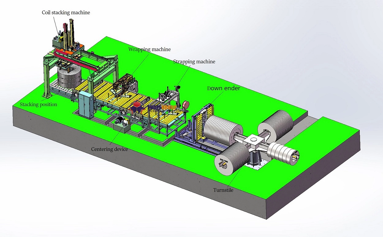
Now we build the logic. The goal is a smooth, uninterrupted material flow where the coil moves in one direction, with minimal waiting and zero manual re-positioning. Think of it as a disciplined assembly line, not a storage yard.
The optimal flow is a straight or L-shaped line that physically separates “clean” packed zones from “raw” incoming zones, preventing contamination and cross-traffic. This segregation is the single biggest contributor to both safety and efficiency gains.
⚙️ The Essential Module Sequence
Every high-performance line follows this core logical sequence. Your layout is the physical manifestation of this process.
-
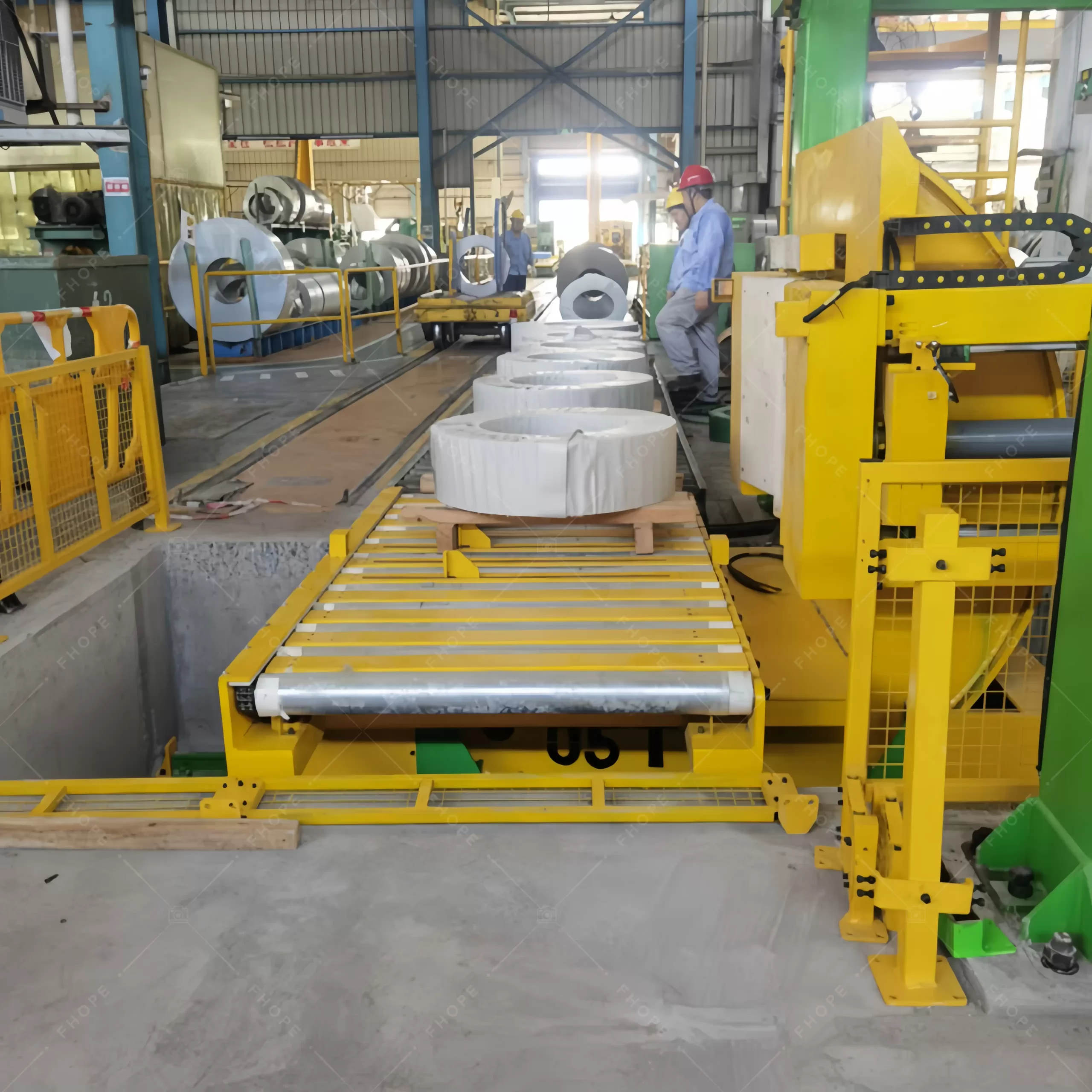
Receiving & Pre-Staging: The starting point. This area must buffer at least 2-3 coils to decouple the line from upstream variability.
-
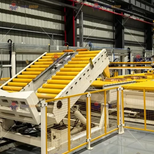
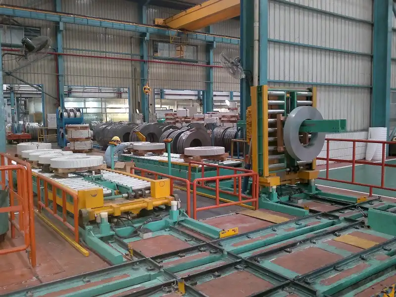
Positioning & Tilting: Here, a Coil Upender or tilter rotates the coil from its shipping (horizontal) orientation to its working (vertical) orientation. This is a non-negotiable safety step for stable wrapping.
- Key Metric: Hydraulic 90° flip within 15-20 seconds with <0.5mm coil face runout.
-
The Packaging Core: The heart of the line.
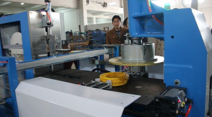
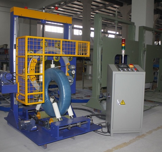
- Wrapping Station: The coil is wrapped with multiple layers of stretch film or protective paper. Look for pre-stretch rates above 300% and consistent web tension control.
- Top/Bottom Protection Application: A head applies composite caps, cardboard, or plastic discs to the coil faces. Precision here is critical for edge protection.
- Band/Side Protection: Steel or plastic strapping is applied, or side protectors are fitted.
Expert Pro Tip: Always place the strapping station after the top/bottom applicator. This secures the face protection in place. Reversing this order is a common, costly mistake that leads to protection failure in transit.
-
Labeling & Discharge: The packed coil is weighed, labeled, and moved to a final staging area for pickup.
📊 Layout Comparison: The Three Core Configurations
Your space and flow goals will lead you to one of these primary layouts.
| Layout Type | Best For | Key Advantage | Key Consideration |
|---|---|---|---|
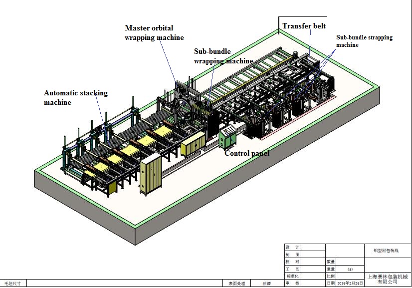
| Straight-Line (In-Line) | High-throughput facilities with long, narrow spaces. | Simple, predictable flow. Easy for operators to monitor entire process. | Requires the most linear floor space. Inflexible for adding future modules. |
| L-Shaped | Most common. Efficient use of corner space. | Excellent separation of raw inbound and finished outbound lanes. Perfect for tight footprints. | Requires a precise 90-degree transfer (often a turntable). More complex controls. |
| U-Shaped | Extremely limited space with same-side input/output. | Maximizes machine density in a small area. | Congested traffic flow. Higher risk of confusion between packed/unpacked coils. |
Phase 3: The Digital Twin – Modeling & Simulation
You have a plan on paper. Now, stop. Building a physical line based on 2D drawings is a gamble. Today, the “first build” must happen in software. This is where you pressure-test your ideas before a single bolt is turned.
Using 3D simulation software is the definitive step to eliminate costly interferences and validate cycle times, turning your layout plan from a diagram into a predictive digital twin of your operation.
🛠️ Validating the Physical Envelope
A 3D model answers critical questions that 2D plans cannot.
- Swept Path Analysis: Does the robot arm or turntable clear the overhead crane rail? Will the coil, when tilted, hit a support column?
- Maintenance Access: Can a technician comfortably reach the hydraulic valves or film roll spindle? Simulate a human model for key service tasks.
- Operator Safety Zones: Visually establish and lock in the safety perimeter fences or light curtains as per ISO 13855 (Safety of machinery).
⚙️ Simulating the Dynamic Process
This is where you prove your throughput (TPH) target.
- Cycle Time Validation: Run the simulation at maximum speed. Does the wrapping station finish before the next coil arrives from the tilter? Identify the bottleneck module.
- Buffer Sizing: How much buffer space is needed before the strapper to maintain flow if a strap fails to feed? The simulation gives you a data-driven answer.
- Traffic Flow: Animate the forklift paths. Do they intersect? Is there enough room for a sideloader to maneuver at the exit?
Phase 4: The Final Checklist – Budget & Future-Proofing
The technical design is solid. Now we align it with business reality. The budget isn’t just for the machines—it’s for the entire system’s lifecycle. And a good design plans for tomorrow’s product mix, not just today’s.
Your final budget must include a minimum 15-20% contingency for foundational work, utilities, and integration. The most common cause of project overrun is discovering poor soil conditions or inadequate electrical supply after the line is designed.
🛡️ The Hidden Cost Lines
Don’t be caught off guard.
- Foundations & Flooring: Heavy tilters and wrappers require reinforced concrete pads (often >300mm thick) with precise flatness tolerances (<3mm over 10m).
- Power & Controls: High-horsepower motors need proper cabling. A central PLC control cabinet with IEC/EN 60204-1 compliance is a must for safety and reliability.
- Installation & Commissioning: Factor in 2-4 weeks for a skilled installation team, including alignment, software tuning, and production trials.
⚙️ Designing for Flexibility & Growth
Your line is a 10-year investment. Build in agility.
- Modular Frame Design: Choose machines built on a standardized, bolt-together frame. This allows you to physically reconfigure or extend the line in the future with minimal downtime.
- Control System Scalability: Ensure the main PLC has spare I/O points (at least 20%) and communication ports. Can it easily integrate a future coil wrapping machine or a second strapping head?
- Quick-Change Tooling: For lines handling varied coil IDs, invest in automatic centering mandrels or quick-release adapters. Aim for product changeovers under 5 minutes.
ROI Insight: The cost of future-proofing (modular design, extra PLC capacity) is typically less than 5% of the total project cost. The cost of not doing it—tearing up floors, rewiring entire panels—can be 50% or more of the original line cost.
Conclusion: From Blueprint to Bottom Line
Designing an efficient coil packing line is a disciplined process of translating operational goals into physical and digital reality. It moves from a thorough audit of your own constraints, through the logical architecture of material flow, into a rigorous 3D simulation that eliminates risk. The final step is a budget and design that embraces both hidden costs and future growth.
Remember, you are not just buying machines; you are architecting a system. The goal is a line that runs with minimal intervention, protects your product value, and adapts as your business grows. By following this structured approach, you move from hoping for efficiency to engineering it into the very floor plan of your operation. And when it’s time to select the core packaging unit, a robust coil wrapping machine will be the reliable heart of this well-planned system.