Designing Your Factory Layout: How to Integrate an Automatic Coil Wrapping System?
As a factory manager, you know every square foot of your floor space is valuable. You face constant pressure to boost output, cut costs, and keep everyone safe. The decision to add an automatic coil wrapping machine is a smart move toward solving these challenges. But simply buying the machine isn’t enough. The real key to unlocking its full potential lies in how you integrate it into your existing workflow. A poor layout can create new bottlenecks, while a thoughtful design turns this equipment into a powerhouse for efficiency.
Integrating an automatic coil wrapping system successfully requires a strategic approach to your factory layout, focusing on seamless material flow, operator safety, and future scalability. It’s not just about placing a machine; it’s about designing a cohesive packaging cell that connects your production line to your shipping dock with maximum efficiency and minimal manual handling. This planning phase is critical for achieving the return on investment you expect from automating your steel coil or wire coil packaging process.
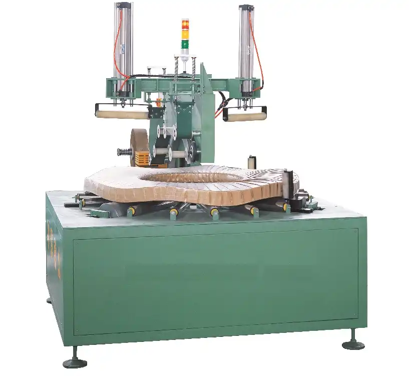
You might be wondering where to even begin. Should the machine go at the very end of the line? How much space do you really need? What about power and air supply? This article will guide you through the essential steps, drawing from two decades of experience in helping factories like yours transform their packaging operations. We’ll move from the big-picture questions down to the practical details, ensuring your new system works in harmony with your entire production flow.
1. Why is Pre-Installation Planning the Most Critical Step?
Imagine receiving a large, complex machine only to find there’s no clear path to get it to its designated spot. Or discovering the electrical supply point is on the opposite side of the building. These scenarios lead to costly delays and frustration. Pre-installation planning is your blueprint for success. It transforms the installation from a chaotic event into a smooth, scheduled project. This phase is where you identify all potential obstacles and requirements before the machine ever arrives at your dock.
Thorough pre-installation planning is critical because it mitigates risk, controls costs, and ensures a smooth startup. It involves a detailed assessment of your site, utility requirements, and material flow paths to create a seamless integration plan. Skipping this step often results in unexpected expenses, prolonged downtime, and a system that never performs to its full capability. A well-planned installation sets the foundation for years of reliable, high-performance operation.
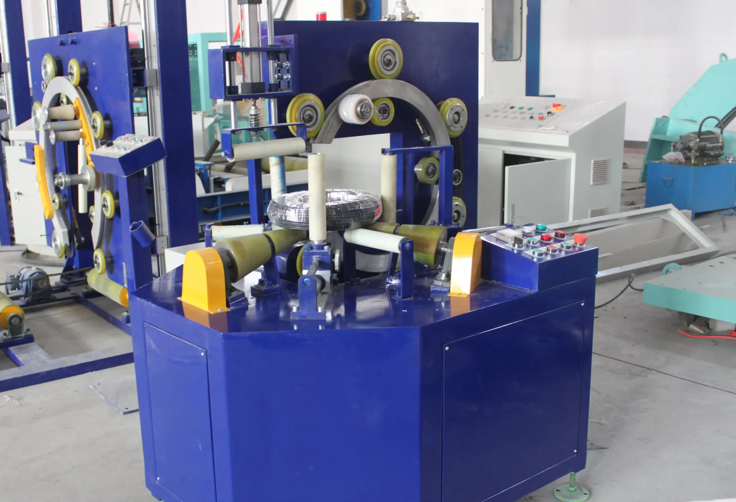
A comprehensive plan covers several key areas. Let’s break down what you need to prepare.
Site Assessment & Space Allocation
First, you must audit the physical space. This isn’t just about the machine’s footprint.
- Machine Footprint: Obtain the exact dimensions (Length x Width x Height) from your supplier, including all guarding and open doors.
- Clearance Zones: Account for safety perimeters, operator panels, and maintenance access. Don’t forget the space needed for the film carriage to travel or for a turntable to rotate.
- Material Handling Space: Calculate the area needed for incoming coils (from production) and outgoing, wrapped pallets (to staging/shipping). This includes space for forklift maneuvering.
- Pathway Analysis: Map the entire route from the machine’s delivery point to its final location. Check door widths, ceiling heights, and floor load capacities along the way.
| Planning Factor | Key Questions to Answer | Potential Risk if Overlooked |
|---|---|---|
| Physical Access | Can the machine fit through all doors and corridors? Is the floor strong enough? | Costly disassembly/reassembly; structural damage. |
| Utilities | Where are the power, compressed air, and data lines? Are they the correct specification? | Need for expensive extensions; machine cannot start. |
| Material Flow | How will coils arrive? How will wrapped pallets exit? Is the flow logical? | Creates new bottlenecks; increases manual handling. |
| Future Expansion | Is there room to add a second line or a pallet conveyor later? | Limits growth, leading to another costly relocation. |
Utility & Infrastructure Audit
Your new wrapping system will need resources. Confirm these details with your supplier early.
- Electrical Power: What is the required voltage (e.g., 480V 3-phase), amperage, and plug type? The location of the main disconnect and control panel is crucial.
- Compressed Air: Most stretch wrapping systems use air for brakes, clamps, and film carriage movement. Check the required PSI, CFM (cubic feet per minute), and air quality (need for dryers/filters).
- Network Connectivity: Will the machine connect to your Plant Floor Network (PFN) or Manufacturing Execution System (MES) for data tracking? Plan for Ethernet cabling.
- Lighting & Environment: Ensure the area has adequate lighting for operators and is free from excessive dust or moisture that could affect sensors and electronics.
Creating a Project Timeline
Treat the integration like any other capital project. Develop a timeline with clear milestones:
- Finalize Layout Drawings (Week 1-2)
- Prepare Site (Utility drops, floor marking) (Week 3-4)
- Machine Delivery & Unloading (Week 5)
- Rigging & Placement (Week 5)
- Utility Connection & Commissioning (Week 6)
- Operator Training & First Article Run (Week 6)
By answering these questions on paper first, you avoid solving them under the pressure of a truck waiting at your gate. A reliable partner like Fengding excels at providing detailed installation manuals and site checklists, making this pre-planning phase much more manageable.
2. How Do You Optimize Material Flow Around the New System?
A machine that runs fast is useless if coils are waiting to be loaded or finished pallets are blocking the exit. The goal is a continuous, smooth flow of material with minimal waiting and zero backtracking. Optimizing material flow reduces cycle time, minimizes forklift traffic (and associated risks), and maximizes the throughput of your new investment. Think of the wrapping station not as an isolated island, but as a vital bridge between your production and shipping departments.
Optimizing material flow involves designing a logical, unidirectional path for coils from the production line, through the wrapping process, and out to staging. This is achieved by analyzing current workflows, defining clear inbound and outbound lanes, and implementing supportive material handling equipment like conveyors or turntables to reduce manual intervention and forklift congestion. The best layouts often adopt a simple “straight-line” or “U-shaped” flow to prevent cross-traffic.
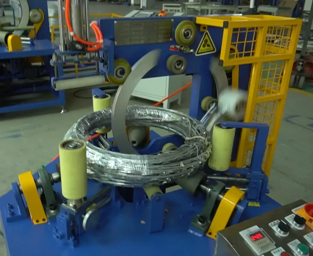
To achieve this, you need to map the journey of a single coil from start to finish.
Mapping the “Product Journey”
Follow a coil from the moment it is finished on the production line until it is safely loaded onto a truck.
- Point of Origin: Where does the finished coil come from? (e.g., cooling bed, conveyor exit, crane drop-off point).
- Transport to Wrapper: How does it get to the wrapper? (Forklift, overhead crane, roller conveyor). Is this path direct?
- Inbound Queue / Pre-Staging: Is there a designated waiting area for coils before wrapping? This buffers against production surges.
- Loading Zone: The space where the coil is placed onto the wrapper’s mandrel or turntable. This area must be clear and safe for the operator.
- Wrapping Cycle: The machine’s operation time.
- Unloading Zone: Where the wrapped pallet is removed.
- Outbound Staging: Where wrapped pallets are temporarily stored before shipping.
- Final Transport to Shipping: The path to the loading dock.
Look for bottlenecks at each stage. Is the forklift driver waiting for the machine to finish? Is the machine waiting for the next coil? The ideal state is a steady, paced flow.
Implementing Flow-Enhancing Equipment
Sometimes, optimizing flow requires adding more than just the wrapper itself. Consider these aids:
- Infeed/Outfeed Conveyors: These create a “hands-off” transfer of coils and pallets, drastically reducing forklift involvement and cycle time. A roller conveyor is common for heavy coils.
- Turntables or Positioners: These devices rotate the coil for optimal loading or allow the forklift to drop the coil and leave immediately, increasing driver efficiency.
- Clear Lane Marking: Use floor tape, paint, or barriers to create dedicated inbound and outbound lanes. This prevents forklift collisions and confusion.
- Digital Andon Lights: Simple traffic light systems (red/yellow/green) can signal the machine’s status to forklift drivers from a distance, so they know when to approach.
The principle is to reduce touchpoints. Every time a human or forklift handles the product, you add time, cost, and risk. A supplier with deep application knowledge, like Wuxi Buhui, can often suggest clever layout tweaks and standard auxiliary equipment that dramatically improve flow based on their vast project history.
3. What Are the Essential Safety and Ergonomic Considerations?
In a heavy industrial environment, safety is not a feature—it is the foundation. An automatic wrapping system removes workers from the most dangerous manual tasks, but it introduces new equipment with its own set of hazards: rotating parts, heavy loads, and powerful motors. Furthermore, the areas around the machine see increased forklift traffic. Your layout must proactively address these risks to protect your most valuable asset: your people. A safe design is also an efficient one, as it prevents accidents that cause downtime, damage, and human tragedy.
Essential safety and ergonomic considerations for integrating a coil wrapper include installing comprehensive machine guarding, designing clear and safe traffic patterns for material handling equipment, and ensuring all operator interfaces are within easy reach and view to prevent awkward postures and strains. The layout must enforce separation between personnel and moving machinery and vehicles. Compliance with local regulations (like OSHA in the US or NOM in Mexico) is the bare minimum; best practice is to exceed them.
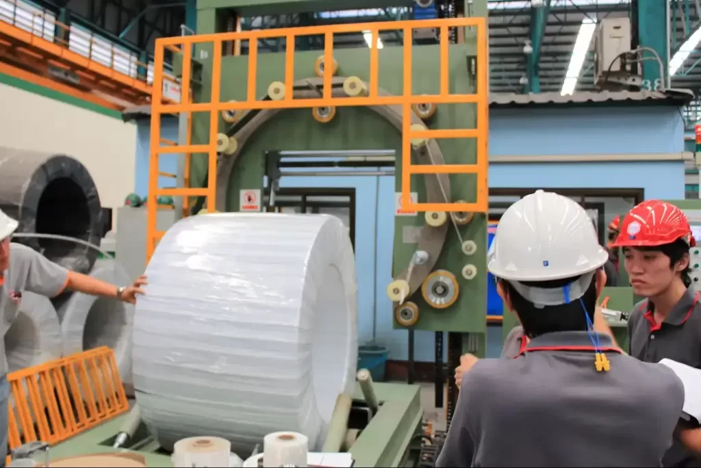
A multi-layered safety approach is most effective. Let’s look at the key layers.
Layer 1: Machine-Centric Safety (Guarding & Controls)
This layer focuses on protecting anyone near the machine itself.
- Fixed Guards: Permanent barriers around rotating turntables, the film carriage track, and pinch points. These should be made of sturdy mesh or solid metal.
- Interlocked Guards: Gates or doors that, when opened, automatically cut power and stop all machine motion. These are crucial for maintenance access.
- Emergency Stop (E-Stop) Buttons: Brightly colored, mushroom-head buttons must be placed at every operator station and at intervals around the machine perimeter. When pressed, they halt all energy to the machine.
- Safety Light Curtains or Laser Scanners: These create an invisible barrier. If breached while the machine is running, they trigger an immediate stop. Ideal for protecting the loading/unloading zone.
Layer 2: Zone & Traffic Safety
This layer manages the interaction between the machine cell and the rest of the factory.
- Defined Pedestrian Walkways: Use painted lines, railings, or elevated walkways to create safe paths for workers that are completely separate from forklift routes.
- Forklift Traffic Management: Establish one-way systems, speed limits (marked with signs), and designated loading/unloading zones with clear sightlines. Mirrors can be installed at blind corners.
- Adequate Lighting: The entire cell, including floor areas and the machine itself, must be well-lit to prevent trips, falls, and misjudgments.
- Floor Condition: Ensure the floor is level, clean, and free of oil or debris that could cause slips, especially in high-traffic areas.
Layer 3: Ergonomic Design for Operators
Even automated systems require human interaction for setup, monitoring, and maintenance. Design these tasks to be easy on the body.
- Control Panel Placement: The Human-Machine Interface (HMI) screen and buttons should be mounted at a height and angle that allows for comfortable viewing and operation without bending or stretching.
- Tool and Consumable Storage: Provide nearby storage for stretch film rolls, tools, and documentation. This prevents clutter on the floor and saves time.
- Maintenance Access: Design the layout so that technicians can easily reach lubrication points, filters, and electrical panels without contorting themselves or using makeshift platforms.
A safe and ergonomic layout isn’t an extra cost; it’s an investment in continuous, uninterrupted production and a positive workplace culture. Leading manufacturers prioritize these features in their standard designs.
4. How Can You Future-Proof Your Layout for Scalability?
The business decision you make today should support the growth you plan for tomorrow. A layout that is perfectly optimized for your current 8-hour, single-shift operation may become a major constraint if you need to add a second wrapper, increase to 24/7 production, or integrate with a new automated storage system. Future-proofing is about building flexibility and optionality into your initial design. It means spending a little more time and thought upfront to avoid the massive cost and disruption of relocating or reconfiguring your entire packaging line down the road.
You can future-proof your factory layout for scalability by allocating extra space for a potential second machine, ensuring utility connections have spare capacity, and designing a modular workflow that can easily integrate with advanced material handling systems like Automated Guided Vehicles (AGVs) or warehouse management software. The goal is to create an adaptable packaging cell, not a fixed installation. This forward-thinking approach protects your capital investment and supports business expansion.

Future-proofing involves strategic decisions in three main areas: space, utilities, and technology.
Strategic Space Allocation
When marking out the floor for your first machine, think about the second one.
- The “Mirror Image” Concept: Position your first wrapper so that a second, identical machine could be placed right next to it, sharing a common infeed or outfeed conveyor. Leave the necessary footprint clear, even if you use it for temporary staging for now.
- Expansion Pathways: Ensure there is a logical direction for the line to grow. If you place the first machine in a dead-end corner, adding a second becomes nearly impossible without moving the first.
- Buffer Zone Sizing: Design your inbound coil staging and outbound pallet staging areas to handle not just today’s volume, but projected future increases. Running out of staging space is a common and costly bottleneck.
Utility Capacity Planning
Your electrical, air, and data lines should not be sized “just right” for today.
- Electrical Panel & Conduit: Work with your electrician to install a panel and run conduit that has spare breaker slots and wire capacity to support an additional machine. It is far cheaper to run a larger conduit once than to tear up the floor twice.
- Compressed Air Header: Size the main air supply line to your packaging area to deliver double the required CFM. Install tee fittings with capped ports at strategic points where a second machine could connect.
- Data Infrastructure: Run extra Ethernet cables or conduit to the machine location. Even if you don’t use them now, having them in place makes connecting a second machine or adding network sensors simple.
Designing for Advanced Integration
The future of manufacturing is connected and data-driven. Your layout should facilitate this.
- AGV-Friendly Flooring: If you anticipate using Automated Guided Vehicles (AGVs) to transport coils or pallets, ensure your floor is smooth, level, and free of major cracks or transitions that could disrupt their navigation.
- Standardized Communication Protocols: Choose a coil wrapping machine from a manufacturer that uses open, industry-standard communication protocols (like OPC UA, Modbus TCP/IP). This ensures it can “talk” to your MES, ERP, or future automation systems without expensive custom interfaces.
- Modular Conveyor Design: If using conveyors, select a modular system that can be easily extended, rerouted, or connected to new equipment in the future.
By incorporating these principles, you’re not just solving today’s problem. You’re building a scalable asset that will support your productivity and profitability for the next decade. This is the hallmark of working with a true partner who understands industrial growth, not just a vendor selling a box.
Conclusion
Integrating an automatic coil wrapping system is a strategic project that extends far beyond the machine itself. Success hinges on meticulous pre-installation planning, a relentless focus on optimizing material flow, an uncompromising commitment to safety, and the foresight to design for future growth. By treating the layout as a critical component of the investment, you transform a powerful piece of equipment into a seamless, high-performing extension of your production line. This holistic approach ensures you achieve the efficiency gains, cost savings, and safety improvements that justify the move to automation. For a reliable and expertly engineered solution, partnering with a proven manufacturer like coil wrapping machine is the first step toward a future-proof packaging operation.