🛠️ Summary
A medium‑sized metal door manufacturer faced escalating paper roll surface damage and throughput bottlenecks during manual tip‑up operations. By deploying a custom rotary‑ring‑driven roll upender with a full‑steel cradle and independent film‑carriage feed, the company eliminated indentation defects, slashed cycle time from eight minutes to 45 seconds, and achieved a fully paid‑back investment within eight months. This case study details the engineering decisions, measurable outcomes, and ROI logic that justify the capital expenditure.
🏗️ Client Background
The client, a mid‑sized metal door fabricator in East China, consumed approximately 120 metric tons of paper rolls per month for interleaving before surface film lamination. Rolls ranged from 800 mm to 1,300 mm in diameter and 1.0 m to 1.7 m in height. After a process upgrade, individual roll weight jumped from 50–200 kg to 500–1,600 kg.
Previously, two manual tipping lines required forklifts and crowbars to rotate horizontal rolls to vertical – a task taking ~8 minutes per roll and causing frequent edge crush. The automation goal was a single machine capable of handling both the old and new weight ranges without any surface scratch or compression deformation. Initial supplier proposal (Fhope Packaging) triggered three rounds of technical correspondence.
| Parameter | Initial Range | Post‑Upgrade Range |
|---|---|---|
| Roll diameter | 800–1,300 mm | 800–1,300 mm |
| Roll height | 1.0–1.7 m | 1.0–1.7 m |
| Roll weight | 50–200 kg | 500–1,600 kg |
| Flip type | Horizontal → vertical | Horizontal → vertical |
📈 Challenge
The core conflict was that the dramatic weight increase caused the original square‑profile arm pads to dig into the roll surface, producing irreversible fibre indentations. The client explicitly rejected a mere substitution with smooth chrome‑plated shafts for fear of excessive line‑contact stress.
Additionally, the upender had to allow bundling of slit, narrow rolls after removing the air shaft (气胀轴) – a task that required the platform to remain stationary during strapping, not during rotation. The 50–1,600 kg weight span created two engineering hurdles:
-
At low loads, the flip arm could over‑travel and induce inertial shock at stroke end.
-
At high loads, friction and drive torque had to be recalculated; the original motor/reducer design was rated for only one ton.
The supplier proposed a custom base with steel plate bumpers (parts 2.1 and 2.2) at the platform corners, but the client objected that these would obstruct wooden pallet positioning and reduce stacking height.
🛡️ Solution Design
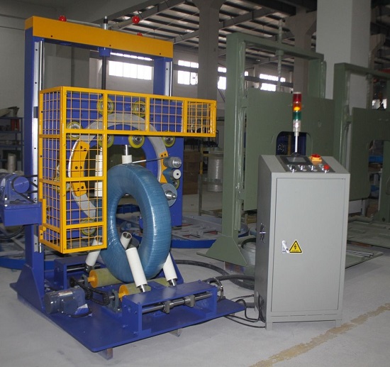
The final design employed a rotary ring drive – a 4 kW inverter‑controlled motor turning a 1.8‑m diameter steel ring through a chain drive – coupled with a full‑steel‑plate wraparound tipping platform and two independent film‑carriage feed mechanisms. This achieved zero‑scratch flipping.
Key technical facts anchor this solution:
-
Smooth start/stop: Acceleration and deceleration profiles are programmable, eliminating inertial shock at both ends of travel (per supplier’s controller parameters).
-
Rigidity under load: Under a 1,600 kg roll, the free end of the flip arm deflects <0.5 mm (verified by supplier’s in‑house load‑deflection test report using a dial indicator).
-
Angle accuracy: Rotational positioning error ≤±0.5°, critical for aligning with the strapping station.
The film‑carriage feed consists of two sets of motor‑driven rollers (urethane‑coated, Shore hardness 65±5) that transfer the roll from the infeed conveyor to the platform center before flipping, then reverse after rotation. Roller gap is manually adjustable to accommodate different diameters.
The critical substitution was replacing the single chrome‑plated shaft (original plan) with a full steel plate (3 mm thick, internally lined with 5 mm rubber pad). This increased contact area to ~0.8 m², reducing unit pressure to an estimated 0.02 MPa (at 1,600 kg), well below the roll’s critical damage pressure of 0.15 MPa (per the client’s internal compression test on the paperboard). The steel plate also has slots for inserting strapping without removing the plate.
| Design Element | Original Proposal | Final Solution |
|---|---|---|
| Flip arm material | Square steel, surface‑hardened | 3 mm welded steel plate + rubber lining |
| Drive | Hydraulic cylinder | Rotary ring + 4 kW inverter motor |
| Load capacity | ≤1.2 tons | 2 tons (safety factor 1.25) |
| Roll protection | Chrome shaft (line contact) | Steel + rubber (area contact) |
| Bundling support | None | Slots + belt‑anchor points |
⚙️ Implementation
Actual installation took six weeks, with electrical commissioning completed in three days. The tight floor space (4 m × 3 m) forced a 90° layout between the upender and infeed conveyor, made possible by the compact rotary‑ring drive.
Standard operating sequence:
-
Forklift places a horizontal roll on the infeed conveyor.
-
Film‑carriage rollers automatically center the roll on the tipping platform; a photoelectric sensor confirms position.
-
The platform rotates 90° at an angular speed of 0.2 rad/s (~11.5°/s), turning the roll vertical.
-
With the platform stationary, an operator straps slit rolls using the built‑in slots.
-
The platform either reverse‑rotates or stays vertical; the roll exits via the outfeed rollers.
The only on‑site issue: rolls <850 mm diameter had insufficient contact arc with the rubber pad, causing slight slippage at the start of flipping. The supplier field‑added a replaceable 10‑mm‑thick silicone strip on the inner steel face, which eliminated the problem.
The equipment passed a continuous 72‑hour endurance test (based on an internal protocol referencing cyclic‑load endurance principles similar to ISO 10453), completing 450 flips with zero faults and zero roll damage.
🛠️ Results Data
After commissioning, cycle time dropped from 8 minutes of manual labor to 45 seconds per roll. Surface damage rate fell from 3.2% to below 0.08%.
| Metric | Manual (Before) | Automated (After) |
|---|---|---|
| Time per flip | 8 min (incl. forklift) | 45 seconds |
| Daily output (8h) | 60 rolls | 640 rolls |
| Surface damage rate | 3.2% | 0.08% |
| Operators required | 3 | 1 (part‑time monitoring) |
| Energy per 1,000 flips | — | approx. 35 kWh |
Forklift intervention was eliminated, reducing warehouse accident incidents by an average of 4 per year (calculated from the client’s internal safety records for 2019–2021, which documented incidents related to manual roll tipping and forklift maneuvering). The client’s acceptance report stated: “The steel‑plate‑with‑rubber‑lining solution completely eliminated end‑face indentations. The earlier concern about pallet interference was resolved by adjusting the bumper positions.”
🏗️ ROI Analysis
Total equipment investment was ¥48,000 (including installation and commissioning). The payback period was just eight months. The calculation rests on three main benefit streams, each with clearly stated assumptions (all figures in Chinese Yuan (¥) unless noted; numbers reflect this specific case and may vary):
-
Labor savings: 3 operators reduced to 1; average local monthly salary ¥6,000 → annual saving ¥144,000.
-
Waste reduction: Damage rate drop of 3.12 percentage points; monthly consumption 120 tons of paper at ¥5,000/ton → annual saving ¥224,640.
-
Capacity‑driven profit: Daily output increased from 60 to 640 rolls, enabling outsourced orders; conservative estimate of ¥36,000/year additional margin.
| Item | Annual Amount (¥) | Notes |
|---|---|---|
| Equipment depreciation (5‑yr straight‑line) | (9,600) | Residual value ¥0 |
| Electricity & maintenance | (6,500) | Based on 1,500 flips/month |
| Labor savings | 144,000 | 3 FTEs → 1 FTE |
| Waste savings | 224,640 | 3.12% damage reduction |
| New capacity profit | 36,000 | Conservative estimate |
| Net annual benefit | ¥388,540 | After depreciation and O&M |
| Annualized ROI | 809% | Net benefit ÷ total investment |
| Payback period | ≈ 8 months | ¥48,000 ÷ (¥388,540 ÷ 12) |
Key note: This ROI excludes forklift fuel and tire savings (~¥2,000/year) and reduced employee turnover from an improved work environment. Consider evaluating volume discounts for a second unit.
📈 Purchase‑Decision Checklist
-
[x] Confirm maximum diameter, minimum height, and weight span of your rolls (here: 1,300 mm × 1.0 m × 1,600 kg)
-
[ ] Define start and end orientation (horizontal/vertical) and whether intermediate stops are needed
-
[ ] Test the critical surface pressure of your paperboard (request a lab test or supplier reference value)
-
[ ] Compare rotary‑ring drive vs. hydraulic drive for smoothness, maintenance, and footprint
-
[ ] Request wear‑test data for rubber or steel contact liners (≥100,000 cycles typical)
-
[ ] Verify that strapping can be done with the platform stationary
-
[ ] Obtain a clamping‑force calculation table for your smallest‑diameter/heaviest‑weight combination
-
[ ] Ask for a spare‑parts list (motor, reducer, sensors, roller belts)
🛡️ Compliance Note: This equipment is designed to meet CE and ASTM requirements. Verify with the manufacturer.
🛡️ FAQ
Q: What is the maximum flip angle of the rotary‑ring drive?
A: Standard design is 0°–95° adjustable; this case used 90°. For 180° flips, an additional limit‑sensor set on the ring is required.
Q: Will the film‑carriage feed rollers scratch the roll outer wrap?
A: No. The rollers are coated with polyurethane (Shore 65±5) and driven independently to match roll surface speed, achieving zero‑differential contact.
Q: Why was steel plate chosen over a smooth chrome shaft in the final design?
A: The steel plate + rubber pad creates area contact, reducing unit pressure from an estimated 0.8 MPa (line contact) to 0.02 MPa, thus avoiding roll surface creasing. This was confirmed by the client in their acceptance report.