How to Avoid Common Defects in Slit Steel Coils During Production
Facing frustrating defects in your slit steel coils? Problems like edge wave, camber, and crossbow disrupt downstream processes and inflate costs. Discover proven strategies to prevent these common flaws and boost quality and efficiency in your production line.

Avoiding common defects in slit steel coils hinges on rigorous quality control from master coil inspection through slitting and handling. Key strategies include ensuring master coils are free of crown and edge wave, maintaining precise slitter knife alignment and sharpness, controlling tension during slitting, and implementing proper material handling and storage practices to prevent physical damage and distortion before further processing like roll forming.
These initial steps are critical, but the journey to defect-free production doesn’t end there. Let’s delve deeper into the specific issues and actionable steps you can take at various stages of the process to minimize flaws and maximize yield.
Mastering Quality Before and During Slitting
Slitting steel coils is a fundamental step, yet it introduces opportunities for frustrating defects that plague downstream operations. Understanding the origins of these flaws during the slitting process itself is the first step towards prevention.
Defect prevention in slit steel coils starts with rigorous master coil inspection for crown and edge wave, critical flaws that transfer directly. Precise slitter knife alignment, sharpness, and controlled tension during slitting are essential to prevent camber, crossbow, and poor edge quality. Implementing strict setup procedures, including machine alignment checks and material gauging, ensures high-quality mults for subsequent processes, boosting efficiency and reducing waste.
To truly avoid defects originating at this stage, you must establish stringent control points.
The Hidden Culprits: Master Coil Defects
Often, problems in slit coils aren’t born during slitting but inherited from the master coil. Two primary culprits here are Crown and Edge Wave. Crown refers to a variation in thickness across the width of the coil, usually thicker in the center than at the edges. When a crowned master coil is slit, the resulting narrow coils become wedge-shaped, meaning one edge is slightly longer than the other. This length difference is a direct cause of camber defects, leading to curvature in the slit strip. Edge wave, characterized by ripples along the coil’s edges, also originates from the master coil if the edges are longer than the center. Slitting a coil with edge wave will inevitably result in slit strips with edge wave, impacting downstream processes like roll forming where it leads to edge-waved profiles. Therefore, a critical QC point, often overlooked, is the thorough inspection and control of master coils before they are loaded onto the slitter. Once a defective coil is slit, correcting the resulting issues becomes significantly more challenging, often impossible through tooling adjustments alone.
Precision in Slitting Setup
Even with high-quality master coils, improper slitter setup can introduce defects. Knife edge wear and damage are common issues. Dull or damaged slitter knives don’t cut cleanly; instead, they can pull and tear the material, introducing uneven stresses and potentially causing burrs, ragged edges, or uneven cuts. Regularly inspecting and replacing worn knives, ensuring they are properly ground and balanced, is essential. Misalignment of the slitting heads themselves, along with the entry and exit guides, can lead to uneven slitting, improper tension distribution, and defects like camber and crossbow. Crossbow, where the top surface of the coil strip becomes unequal in length to the bottom surface, is frequently a direct result of incorrect slitter setup causing uneven pressure or tension across the strip width during cutting and recoiling.
Slitting-Induced Defects and Their Impact
Several common defects are specifically generated or exacerbated during the slitting process. Camber is a prevalent one, defined as a gradual deviation from straightness along the edge of the slit strip. It’s essentially an edgewise curvature. While it can stem from master coil crown, it’s also caused by uneven tension or pressure during slitting, or dull knives pulling the material unevenly. Camber in the slit coil stock is a notorious precursor to bow, curve, and twist defects in subsequently roll-formed profiles because the longer edge forces the material to deviate from a straight line. Crossbow, as mentioned, is another direct result of slitter setup issues, often occurring during the coiling process after slitting if tension or pressure is unevenly applied across the width. This defect means the strip has a cross-sectional curvature. If the shorter surface is on the inside radius when coiled, it creates pressure that can lead to oil canning or edge wave defects in the final product, where the center is longer than the edges. Poor slit quality, characterized by excessive burrs or ragged edges, is directly related to knife sharpness and proper clearance. These edge imperfections not only affect aesthetics but can also interfere with downstream feeding, guiding, and forming processes, potentially causing scoring or other surface defects on the finished profile.
| Defect | Description | Primary Cause (Slitting) | Downstream Impact |
|---|---|---|---|
| Crown | Thickness varies across width (inherited) | Previous Rolling Processes | Wedge-shaped mults, Camber |
| Edge Wave | Ripples along edges (inherited) | Uneven length across width (inherited) | Perpetuates into slit material |
| Camber | Edgewise curvature | Uneven tension/pressure, Dull knives | Bow, Twist, Curve in formed profiles |
| Crossbow | Top/bottom surface lengths unequal, cross curvature | Incorrect slitter setup, Uneven tension | Oil canning, Edge wave (in forming) |
| Poor Edge | Burrs, ragged edges | Dull/damaged knives, Improper clearance | Scoring, Interferes with forming |
Addressing these issues requires not only inspecting incoming material but also meticulous slitter setup and maintenance procedures to ensure the slitting operation itself does not introduce or worsen defects.
Residual Stress and Its Release
Steel, by its nature, holds inherent stresses from its production journey. These residual stresses can unpredictably release during slitting and forming, posing significant challenges to achieving consistent quality.
Residual stress, originating from prior cold or hot rolling processes like full-hard or skin rolling, is a major source of unpredictable behavior in slit steel coils. This trapped energy, when unevenly released during slitting or subsequent processing, can cause significant distortion, leading directly to defects like twist, bow, and camber in the final product, making accurate forming challenging for operators.
Working with steel means acknowledging the presence of residual stress, whether the coil is cold-rolled or hot-rolled. This stress is locked into the material during previous reduction processes. For instance, full-hard rolling, which can reduce thickness by around 50%, and even skin rolling, which involves minimal thickness reduction (less than 1%), both generate residual stresses trapped within the coil structure. The challenge for processors, particularly those involved in slitting and roll forming, is that this trapped stress can release unevenly. This unbalanced release is a primary reason why one batch of coil might process perfectly while another, seemingly identical batch, might exhibit slight twist or bow.
The unpredictable nature of residual stress release makes precise forming processes quite challenging. As the material is slit or bent through roll forming dies, the internal forces seek equilibrium, causing the strip to distort. While tension leveling at the mill helps mitigate many imperfections, it doesn’t always eliminate all residual stress, especially transverse stresses. Other material properties also contribute to unpredictable behavior. The natural expansion and contraction of steel with temperature changes can slightly alter dimensions during a production run. Uneven substrate properties within the coil can lead to localized inconsistencies in forming. High yield stress in the material can make it more susceptible to buckling or oil canning defects during processing.
Experienced operators understand the impact of material characteristics beyond just thickness and width. They often perform simple material tests, like bending a sample piece before beginning production, to get an indication of the material’s inherent springiness and how it might react during forming. Furthermore, they anticipate potential issues arising from residual stress and are prepared to make tooling adjustments to prevent or minimize resulting roll forming defects such as twist or bow, which are common manifestations of uneven stress release. While it’s difficult to quantify residual stress precisely without specialized equipment, recognizing its presence and potential impact is crucial for effective defect prevention. This highlights the interdependence between material quality, as delivered in the slit coil, and the downstream process’s ability to produce a quality product.
Machine Alignment and Tooling Precision
Are you battling inconsistent quality and frustrating defects in your slit steel coils’ downstream processing? Misaligned machinery and improper tooling setup are often the silent culprits causing costly errors. Learn how to ensure your roll forming line’s alignment is perfect to unlock precision and eliminate common profile defects.
Achieving defect-free slit steel coil processing, particularly in roll forming, critically relies on machine alignment. Proper setup of entry guides, roller alignment (both horizontal and vertical), and consistent gauging with the actual material are paramount. Neglecting tooling cleanliness, shaft condition, and bearing integrity can introduce unforeseen issues. Regular checks using straight edges and bridge levels, coupled with systematic SOPs, are vital to maintain the precision required for high-quality formed products, directly addressing the root causes of many defects.

Once you have high-quality slit coils, the next major hurdle in achieving a defect-free product lies in the precision of your processing machinery, especially in roll forming. Alignment isn’t just about the rolls; it’s a system-wide consideration.
The Foundation: Equipment and Base Alignment
A fundamental requirement for consistent roll forming is a properly aligned line base. The forming mill base and all auxiliary equipment – including the entry guide stand, weld box, and ironing passes – must be level throughout their length. A non-level base can introduce stresses and misalignments that propagate through the entire line. Beyond the base, the condition of driven shafts is critical. Worn spots, rings, or grooves, particularly where the rolls ride, can cause rolls to run out-of-round, leading to line surge, chatter marks, or ripple defects on the product surface. Undersized or oversized shafts compromise roll fit and function. Chroming is a common technique to restore worn shafts. Bearings also play a vital role; worn or damaged bearings, especially in high-volume production, can lead to vibration and misalignment. Ensuring bearing integrity is a key maintenance check. Finally, correct back shoulder alignment – verifying that the shaft shoulder fits snugly against the inboard stand and that shoulders are consistent in measurement from stand to stand and top to bottom – is essential for repeatable roll positioning.
Tooling Setup and Maintenance
Improper tooling setup is a leading cause of roll forming defects. A common mistake operators make is incorrect alignment of the tooling (rolls) within the stands. Horizontal and vertical alignment must be precise. Another frequent error is adjusting rollers without the coil material in place. Gauging roll gaps without the material, then attempting production, often leads to twist and bow issues. The correct procedure involves initially setting approximate gaps, then putting the actual coil through the first pass, re-gauging the rolls with the material present, and setting final gaps based on the actual coil thickness and observed forming. A test run is essential before mass production begins. Lack of proper lubrication, or using the incorrect type, increases friction and wear, potentially causing rolling marks, uneven forming, and premature tool damage. Cleanliness is also paramount. Roll forming equipment and tooling must be kept free of grit, debris, or material buildup that can alter tooling alignment or damage the material surface. Wiping spacers, shafts, and tooling clean before installation is a simple yet effective preventative measure. Using an inspection mirror and flashlight to visually check if dies are touching the coil helps identify setup errors. Passing gauges through a tooling pass can reveal loose or tight spots indicative of misalignment.
Line-Wide Alignment Checks
Precision extends beyond individual passes. Machine face alignment, often neglected, ensures that all stands and components are squared relative to the material flow line. A simple check with a straight edge across tooling faces can reveal significant issues. The integrity of the entry guide rolls is vital; if the slit coil is allowed to move freely from side to side before entering the first forming pass, camber or twist are highly likely to occur. Driven stands must be aligned with each other – horizontally, vertically, and diagonally. Driven shafts need to be set parallel – base to bottom shaft, bottom shaft to top shaft, and stand to stand. Individual roll dies need to be checked for parallelism and alignment using straight edges and bridge levels. Detecting roll former misalignments can be challenging, but a systematic approach starting with a complete "footprint" of the entire line, from decoiler to the final formed profile, is effective. Every component should be set to a centerline or offset centerline, and each part checked for squareness, parallelism, and perpendicularity relative to others and the centerline. Deviations create pressure on feeding and forming, leading to defects. A Standard Operating Procedure (SOP) for tooling setup and alignment checks allows operators to systematically identify and correct components causing misalignment, ensuring the entire line is aligned, not just measured at points.
| Aspect | Key Check | Importance |
|---|---|---|
| Line Base | Levelness throughout length | Foundation for overall alignment |
| Driven Shafts | Condition (wear), Parallelism | Prevents roll damage, ensures smooth feeding |
| Bearings | Condition | Reduces vibration, maintains accuracy |
| Tooling Alignment | Horizontal, Vertical, Gap with Material | Direct impact on formed profile shape |
| Tooling Cleanliness | Free of grit/debris | Prevents surface marks, maintains alignment |
| Entry Guides | Mechanically tight, Perpendicular to flow | Controls material entry, prevents twist/camber |
| Driven Stands | Horizontal, Vertical, Diagonal alignment | Ensures consistent forming across passes |
| Machine Face | Squareness relative to material flow line | Holistic line accuracy |
| Line Footprint | Centerline, Squareness, Parallelism of components | Identifies systemic misalignment issues |
Handling and Storage Practices
The journey of a slit steel coil doesn’t end after cutting. How these coils are handled, stored, and transported significantly impacts their final quality before they reach the next stage of production.
Proper handling and storage are crucial to avoid damage that leads to defects in slit steel coils. Using appropriate equipment like coil tippers and multidirectional forklifts, ensuring correct weight-to-lift ratios, and minimizing "double-handling" reduces risks. Storing coils correctly, whether "eye to the sky" for finished goods or "eye to the side" for WIP, prevents physical damage like nicks or distortion, maintaining coil integrity until use and safeguarding product quality and worker safety.
Handling coil, whether moving or storing, requires precision to avoid damaging the product or causing injury. Utilizing the wrong equipment or using proper equipment incorrectly can severely impact coil quality. Coils often arrive "eye to the sky," meaning the center is facing upward, delivered on a pallet. To feed a roll former line, the coil usually needs to be "eye to the side." Equipment like coil tippers are necessary to safely reorient the coil. Specialized coil pallets and racking systems designed for eye-to-the-side storage help maintain coil integrity and maximize warehouse space. Efficient coil handlers or multidirectional forklifts are recommended over standard forklifts for swapping coils on a line. These specialized forklifts can lift coils both "eye to the side" or "eye to the sky" by using forks through the eye or lifting via pallets. Crucially, they retract the coil weight (4 to 10 tons or more) between the forklift legs, distributing the weight evenly over the wheels for much greater load stability and safety compared to carrying the load out front.
Storage strategy depends on the coil’s status. Finished coils are often stored "eye to the sky" to protect the painted surface and maximize storage density. However, work-in-progress (WIP) coils intended for immediate processing are typically stored "eye to the side" to facilitate quick loading onto the decoiler mandrel. Minimizing the number of times a coil is handled (avoiding "double-handling") is a key strategy to reduce the risk of damage. Each lift and transport introduces a potential point of failure or impact.
Common hazards are significant due to the extreme weight and size of steel coils. Incorrect weight-to-lift calculations are dangerous. Always use equipment rated for the weight of the coil, never underrated, to prevent equipment failure or dropping the coil, which could be fatal. Fire safety is also critical; communicate coil storage locations and heights to fire inspectors, as burning pallets beneath stacked coils can cause them to fall through walls. Even seemingly simple mistakes like nicking the coil edge or side during movement can damage a significant amount of footage, potentially rendering the entire coil unusable depending on the severity and location of the blemish. Quality control must extend to material handling processes. Ongoing refresher training for equipment operators, especially forklift drivers, is essential to prevent complacency and reinforce safe and precise handling practices, ensuring coils are delivered to the production line in the same condition they were received.
Conclusion
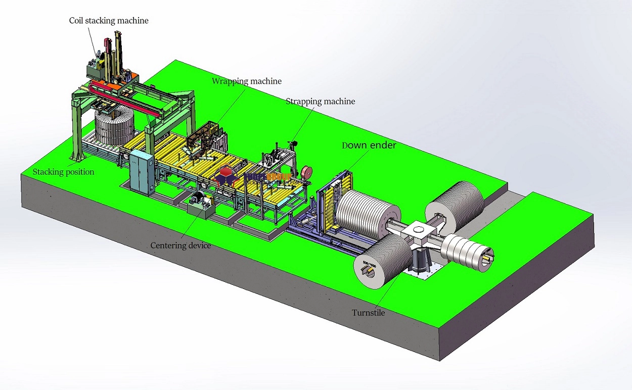
Avoiding common defects in slit steel coils requires a comprehensive approach, spanning initial master coil quality checks, precise slitting operations, managing residual stresses, ensuring rigorous machine and tooling alignment, and implementing careful handling and storage protocols. By focusing on these critical stages and adopting systematic quality control measures, manufacturers can significantly reduce defects like camber, edge wave, and crossbow, leading to improved productivity, reduced waste, and higher product quality. Investing in advanced processes and technologies, such as those used in automated steel coils processing and coil packing line solutions, further enhances reliability and efficiency throughout the production lifecycle.


