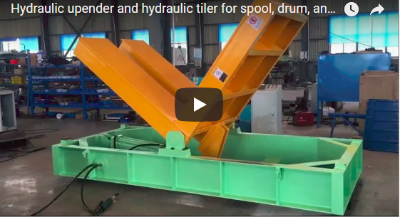
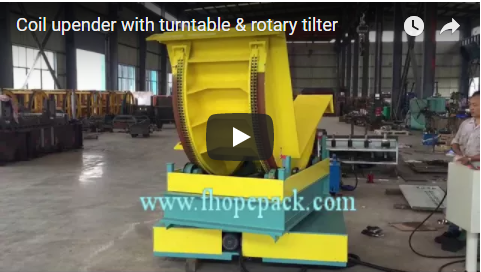
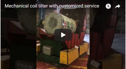
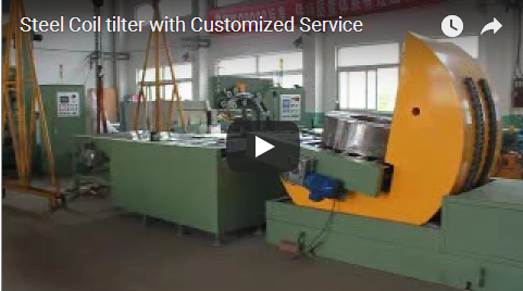
执行摘要 An industrial hydraulic 90° coil tilter (also designated as a hydraulic coil upender) reorients heavy metallic coils between the eye-horizontal (bore-horizontal) and eye-vertical (eye-to-sky) axes via rigid mechanical linkages driven by dual hydraulic cylinders. The integrated adjustable working table provides precise positioning compensation for mixed-diameter and variable-width coil production, preventing eccentric torque loads on the pivot trunnions. The FPCT heavy-duty series covers rated lifting capacities from 2 t to 50 t, achieving controlled tilting cycles within 50–100 seconds per movement under variable proportional pressure control. Critical structural footprints, cradle geometry, and power unit configurations are engineered to specific production envelope dimensions.
Processing facilities and continuous slit-coil packaging lines handling diverse steel, copper, or aluminum coils require an upender capable of adapting without structural changeover downtime. The adjustable working cradle is the primary mechanical assembly that makes broad capacity ranges possible. Constructed as a reinforced L-shaped structural steel frame with an integrated transverse backstop plate, the machine supports the coil along its cylindrical circumference while upright and transitions the total load smoothly onto the horizontal table face. The dedicated hydraulic power unit (HPU) sits independently beside the machine base, isolated from mechanical shock and rotational pivot stresses.
目录
- Why Hydraulic Actuation for Coil Tilting
- Mechanical Role of the Adjustable Working Table
- FPCT Series Technical Specifications
- Model Selection Criteria and Worked Example
- 工程尺寸核对清单
- Safety Systems: EN 415-10 and ISO 12100 Compliance
- 工程常见问题解答
- Procurement and Technical Inquiries
- 相关工业解决方案
- 参考文献和文档
Why Hydraulic Actuation for Coil Tilting
Heavy metallic coils present a dynamic kinematic challenge: as the L-shaped cradle sweeps through its 90° quadrant, the center of gravity (CoG) crosses the pivot centerline (the over-center point). This over-center shift converts the required actuator force from a resistive pushing load into a runaway gravitational pulling load.
   [Eye-Horizontal]                     [45° Over-Center]                  [Eye-Vertical]
       |                                       /                                 _____
      [O] -> Pushing Phase                  [O] -> Critical Zero-Load           | [O] | -> Controlled Holding
     ====\                                 /====                                ======
 Pivot (O)============================= Pivot (O) =========================== Pivot (O)
Mechanical gear drives can experience severe backlash and tooth shock during this gravitational handoff. In contrast, electro-hydraulic systems manage this transition seamlessly through engineered fluid dynamics:
- Over-Center Counterbalance Valve Protection: Dual-pilot-operated counterbalance valves (over-center valves) maintain backpressure on the cylinder rod ends, preventing gravitational runaway, uncommanded descent, or cavitation.
- Terminal Stroke Cushioning: Integrated internal deceleration cushions within the heavy-duty hydraulic cylinders guarantee zero-shock mechanical seating at both the 0° and 90° stops.
- Proportional Motion Control: Tilting speeds and circuit pressures (rated up to 16–21 MPa) are fully modulated at the HPU valve manifold, allowing fragile slit strips and maximum-capacity 50 t master coils to operate within safe structural velocity profiles.
Mechanical Role of the Adjustable Working Table
A standard rigid V-cradle matches only a single nominal coil diameter and width. Subjecting mismatched coil sizes to a non-adjustable table introduces lateral eccentricity, creating severe point loading along the coil edges and inducing unbalanced bending moments on the main pivot trunnions.
POOR PRACTICE: Fixed Table (High Offset)         BEST PRACTICE: Centered Adjustable Table
          +---------------+                                  +---------------+
          |  Coil Mass    |                                  |   Coil Mass   |
          |    (CoG)      |                                  |     (CoG)     |
          +-------+-------+                                  +-------+-------+
                  |                                                  |
                  |<--- Eccentric Arm --->|                          |<-- Balanced ->|
             Pivot Point (High Strain)                          Pivot Point (Zero Moment)
The adjustable working table solves this geometric imbalance:
- CoG Alignment with Pivot Centerline: Adjusting the cradle deck sets the effective center of mass of variable-dimension coils adjacent to the machine’s main axis of rotation, minimizing cylinder stroke thrust demand and reducing structural torsional fatigue.
- Coil Edge and Core Preservation: Uniform support geometry eliminates localized contact indentation on sensitive strip edges, pre-painted finishes, or thin-gauge outer wraps.
- Flexible Positioning Mechanisms: Depending on batch frequency, positioning is accomplished through manual pin-indexed positioning blocks, heavy-duty lead-screw spacers, or automated motor-driven lead-screws linked directly to line PLC recipes.
- Packaging Line Conveyor Integration: The horizontal table face can incorporate driven rollways, walking beams, or motorized pallet conveyors, allowing seamless inline feeding between slitters and downstream automated radial strapping stations.
FPCT Series Technical Specifications
The following parameters outline the standard industrial configuration of the FPCT heavy-duty hydraulic coil upender series:
| 型号 | 最大载重量 | Installed HPU Power | Tilting Cycle (90°) | Main Cylinder Configuration | 液压工作压力 |
|---|---|---|---|---|---|
| FPCT-02 | 2 t (20 kN) | 1.5 kW | 50–70 秒 | Single bore-acting cylinder | 14兆帕 |
| FPCT-05 | 5 t (50 kN) | 1.5 kW | 50–80 秒 | Single heavy-duty cylinder | 16兆帕 |
| FPCT-10 | 10 t (100 kN) | 3.2 kW | 60–90 秒 | Dual synchronized cylinders | 16兆帕 |
| FPCT-20 | 20 t (200 kN) | 4.5 kW | 60–90 秒 | Dual synchronized cylinders | 18兆帕 |
| FPCT-30 | 30 t (300 kN) | 6.5 kW | 60–90 秒 | Dual heavy-duty bore cylinders | 18兆帕 |
| FPCT-50 | 50 t (500 kN) | 11.5 kW | 60–100 秒 | Dual heavy-duty tandem cylinders | 21兆帕 |
Note: Total tare weight, structural bed dimensions, table surface finishes (nylon, hardwood, polyurethane, or steel roller tops), and HPU oil cooler specs are determined by incoming coil geometries.
Model Selection Criteria and Worked Example
Select the tilter capacity based on the absolute maximum gross weight of your coil processing envelope (including inner packaging, strapping, or transport pallets). Never design down to an average batch weight.
       Step 1: Determine Max Coil Mass (M_max) & Gross OD / Width
                                 │
                                 ▼
       Step 2: Check Machine Rating Class (M_max ≤ Model Rating)
                                 │
                                 ▼
       Step 3: Calculate Torsional & Center-of-Gravity Margins
               (Verify Width vs. Adjustable Cradle Travel)
                                 │
                                 ▼
       Step 4: Establish Total Takt Cycle Requirement:
               T_total = T_load + T_tilt + T_unload + T_return
Engineering Sizing Case Study
- Operating Facility: Master coil slitting and automated transfer bay.
- 负载范围: Slit coils from 8.5 t up to peak master weights of 17.5 t; coil outer diameters from 1100 mm to 2100 mm; widths from 450 mm to 1600 mm.
- Model Recommendation: FPCT-20 (20 t rated capacity). Although the 8.5 t coils fall inside the FPCT-10 rating, the 17.5 t peak demands the structural steel cross-section, dual cylinder synchronization, and 4.5 kW power unit of the FPCT-20.
- Takt Time Analysis:
- Forward tilt (90°): 75 s average.
- Return tilt (90°): 65 s average.
- Overhead crane positioning and rigging: 120 s.
- C-hook release and clearance: 40 s.
- Total Floor Cycle Takt: 75 + 40 + 65 + 120 = 300 s (5.0 minutes / 12 coils per hour theoretical maximum).
工程尺寸核对清单
Provide the following design boundary constraints to calculate structural deflection and cylinder sizing:
- 线圈质量范围: Peak gross weight (kg) and minimum processing weight (kg).
- Coil Envelope Dimensions: Minimum/maximum Outer Diameter (OD), Inner Diameter (ID), and axial width range (W).
- Orientation Vectors: Eye-horizontal to eye-vertical (down-ending), eye-vertical to eye-horizontal (up-ending), or bidirectional 2-way turning.
- Loading and Unloading Interface: Overhead bridge crane (C-hook or motorized coil grab), forklift with coil ram/prongs, or driven chain/roller conveyor.
- Target Duty Cycle: Total lifts/cycles per hour and operating shift schedules (e.g., 24/7 continuous mill operation).
- 接口要求: Floor-pit flush mounting vs. surface slab mounting; floor anchoring capacity; ambient temperature extremes for hydraulic fluid grade selection.
Safety Systems: EN 415-10 and ISO 12100 Compliance
Integrated industrial coil upenders pose pinch and crushing hazards under international machinery safety directives. All systems are engineered to harmonized safety standards:
- Structural Integrity and Risk Mitigation (ISO 12100): Comprehensive engineering risk assessments guide structural safety factors (exceeding 2.5:1 on dynamic weldments and pivot shafts).
- Packaging and Integrated Line Machinery Directives (EN 415-10): Specific safety specifications for coil binding and handling integration.
- Hydraulic Line-Rupture Protection: Direct-manifold-mounted pilot-operated check valves and counterbalances freeze the tilting table immediately in the event of upstream hydraulic hose burst or sudden pressure drop.
- Physical Machine Safeguarding: Perimeter safety fencing with Category 4 interlocked access gates, dual-channel E-stop circuits, and optical muting light curtains across loading zones.
- 认证: Machines are factory-tested, CE marked, and manufactured under ISO 9001 certified quality control procedures.
工程常见问题解答
Q: How does the adjustable working table accommodate coils with vastly different widths? A: The table utilizes modular positioning blocks, manual ACME thread adjusters, or motor-driven leadscrews that position the primary cradle face closer to or farther from the rotation axis. This ensures that the coil’s dynamic center of gravity remains centered within the trunnion bearing span, preventing eccentric lateral loading on the cylinder rods.
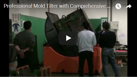
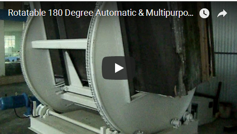
Q: Can this machine be adapted for 180° coil turnover applications? A: No. The standard FPCT series is an L-frame mechanical structure designed specifically for 90° transitions between horizontal and vertical axes. For 180° pallet or mold inversion, a fully enclosed barrel-type or dual-clamping 180° turnover machine is required.
Q: What routine preventative maintenance is mandated for the hydraulic power unit? A: Regularly monitor the sight-glass oil level, monitor filter differential pressure indicators, and inspect all high-pressure hose crimps and trunnion cylinder seals. Hydraulic fluid cleanliness should be maintained at ISO 4406 cleanliness code 19/17/14 or better. Filter elements require replacement after the initial 500 operating hours and every 2,000 hours thereafter.
Q: What factory warranty is provided on structural components and hydraulic actuators? A: All FPCT series machines are backed by a comprehensive 24-month OEM warranty covering the main structural weldments, pivot bearings, hydraulic cylinders, and power unit manifolds against manufacturing defects.
Procurement and Technical Inquiries
To receive an engineering layout and technical proposal:
- Submit Processing Specifications: Forward your coil diameter limits (OD/ID), maximum axial width, peak load weights, and preferred plant layout drawings to: Technical Engineering Office: info@fhopepack.com
- CAD and Circuit Review: Our mechanical engineering team will run your weight envelopes through our load-moment simulation software and define the exact table dimensions and power unit requirements.
- 正式提案提交: Receive a comprehensive technical proposal, including 2D footprint layouts, cycle time analysis, and pricing within 完成。.
相关工业解决方案
- Heavy-Duty Hydraulic Coil Upender Systems
- Custom-Engineered Mechanical Tilt Tables & Mold Upenders
- Mechanical Coil Tilter Field Commissioning and Service Operations
- High-Throughput Automatic Coil Tilter with Integrated Slide Table
参考文献和文档
- FHOPEPACK Mechanical Engineering Database: FPCT Series Technical Specifications.
- ISO 12100: Safety of Machinery — General principles for design — Risk assessment and risk reduction.
- EN 415-10: Safety of packaging machines — Part 10: General requirements.
Last technical review completed by Principal Applications Engineer on: 2026-10-19