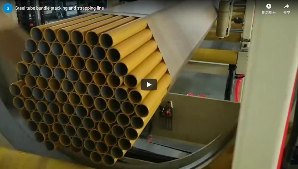
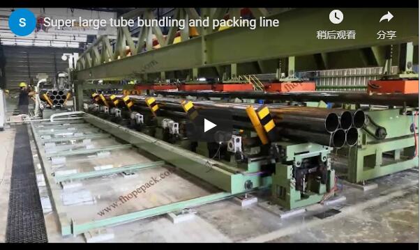
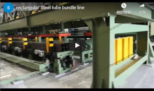
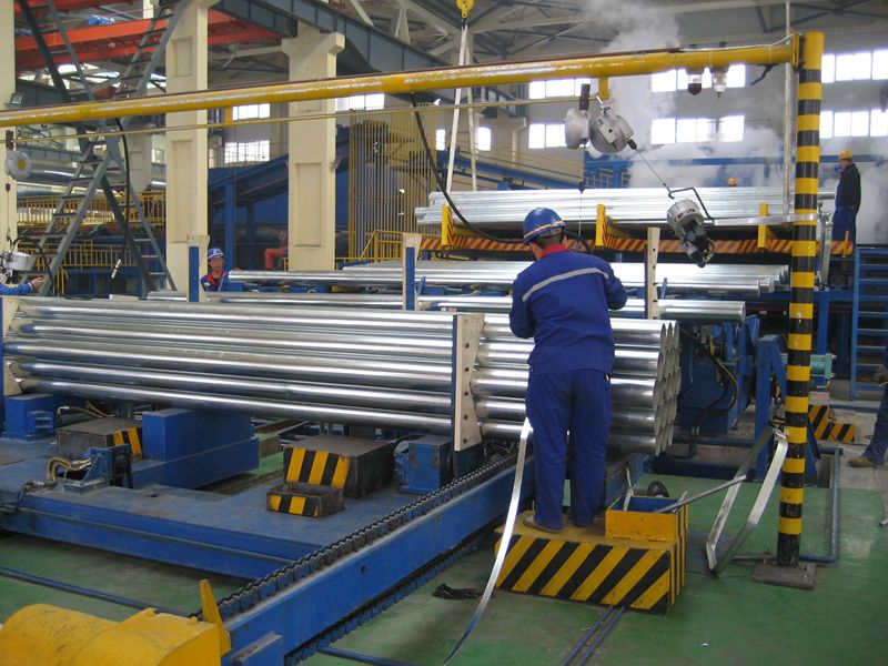
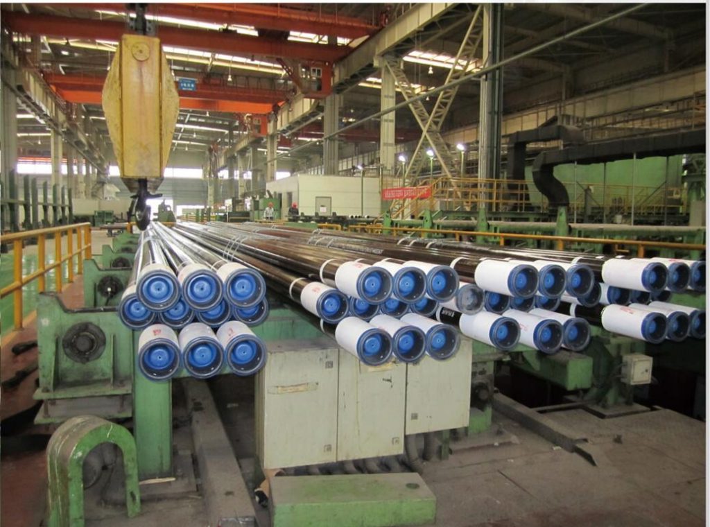
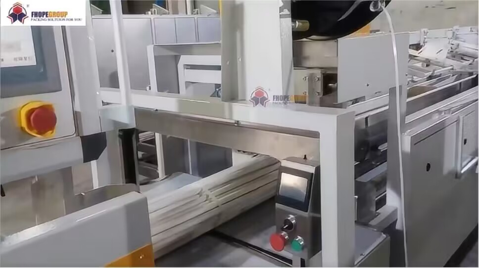
Santrauka An automated steel tube bundle packing line streamlines finishing operations between the mill cut-off station and warehouse dispatch. By automating pipe counting, row layer indexing, symmetrical hexagonal or square bundle forming, and high-tension circumferential strapping, the system eliminates manual handling risks and structural bundle slippage. Operating under central supervisory management with distributed station controls, the line supports automatic, semi-automatic, and manual intervention modes. The processing envelope accommodates round, square, and rectangular structural hollow sections, providing calibrated hydraulic compaction and multi-point steel strapping to secure bundles up to 16 m in length and 13,000 kg in total pack weight.
Eilučių seka
The automated steel tube bundle packaging line operates across three synchronized stations linked by dual-drive roller conveyors and cross-transfer stations:
+—————————————————————————————————+ | THREE-STATION PACKING SEQUENCE | +——————————+ +——————————-+ +————————+ | Station 1: Infeed & Metering | –> | Station 2: Nesting & Clamping | –> | Station 3: Strapping | | Singulation, OD blowdown, | | V-cradle charging, hydraulic | | Circumferential steel | | end-stop squaring, counting | | side & top bundle compaction | | strapping & outfeed | +——————————+ +——————————-+ +————————+
- Station 1 (Infeed, Internal Cleanout & Layer Metering): Finished tubes transfer from the mill run-out table onto heavy-duty accumulation skids. Polyurethane indexing fingers singulate individual tubes, while pneumatic nozzles blow down internal scale and residual coolant. Forward roller conveyors drive the tubes against a solid carbide mechanical end-stop to ensure flush end faces within ±5 mm. Optical through-beam sensors verify tube counts per tier based on the active recipe.
- Station 2 (Hexagonal/Square Nesting & Hydraulic Compaction): Overhead transfer arms lower pre-metered tube tiers into the adjustable V-shaped bundle forming cradle. Once the designated layer matrix settles into a nested orientation, opposed hydraulic side arms and overhead clamps apply uniform radial pressure, consolidating loose tubes into a tightly interlocked geometric bundle.
- Station 3 (Automated Strapping & Longitudinal Transfer): The clamped bundle shifts downstream onto heavy-duty conveyor beds through an automated strapping portal. High-tension circumferential steel bands are indexed and applied along the bundle span before the finished pack discharges to an accumulation buffer for crane removal.
Counting and forming
Achieving stable bundles requires precise counting and repeatable mechanical grouping to prevent shifting during high-speed crane handling.
- Sluoksnio formavimas: Tubes are isolated via mechanical escapements and arranged into predefined horizontal rows. For round tubing, rows follow standard nested progressions (such as 3-4-5-4-3 or 4-5-6-5-4 arrays). For square profiles (90 × 90 mm to 250 × 250 mm) or rectangular hollow sections (80 × 100 mm to 200 × 300 mm), the accumulation bed builds orthogonal grid stacks.
- Forming Bed Kinematics: The forming station utilizes a symmetrical V-bed cradle lined with high-density polyurethane rollers to eliminate surface scoring. Motor-driven lead screws adjust the cradle angle and baseline opening, enabling quick changeovers between hexagonal and rectangular profiles without mechanical teardown.
Tvirtinimo jėga
Once the counted tubes enter the forming station, hydraulic clamping arms swing inward to lock the bundle profile prior to strapping:
- Squeeze Dynamics: Opposed double-acting hydraulic cylinders deliver balanced inward side force while top-mounted vertical cylinders prevent upper-tier tube bucking.
- Surface Protection & Pressure Regulation: System hydraulic pressure is regulated via proportional pressure-reducing valves. Clamping jaws are lined with durable elastomer wear strips to safeguard treated or high-finish pipe walls.
- Structural Lockout: Dual pilot-operated check valves maintain clamping pressure throughout the transfer cycle, ensuring that bundles do not distort before straps are tensioned.
Bundle diameter from tube count
Calculating the cross-sectional envelope of a nested bundle is critical to verify conveyor clearances, strapping chute windows, and downstream handling limits.
For a symmetrical hexagonal pack formed by round tubes of outside diameter d, the overall circumscribed bundle envelope diameter D can be derived from the outer tube layer count n along a single outer boundary:
D ≈ d × (1 + 1 / sin(π / n))
- Skaičiavimo pavyzdys: Consider a standard 7-tube bundle (1 center tube surrounded by 6 outer tubes; where
n = 6outer perimeter points) usingd = 48 mm(Φ48 mm) round tubing:
D ≈ 48 × (1 + 1 / sin(π / 6)) D ≈ 48 × (1 + 1 / 0.5) D ≈ 48 × (1 + 2) = 144 mm (Theoretical maximum envelope vertex) With nested packing contact allowances, the nominal outer diameter consolidates to approximately:
D ≈ 134 mm across flats and crown points This compact geometry provides the rigid, non-shifting foundation necessary for uniform strapping tension.
Strap count and tension
Circumferential packaging integrity depends on applying the correct band pitch and tension to prevent telescoping during flatbed trucking or overseas container shipment.
Strap Count Formulation
The required number of straps along a bundle is determined by the total bundle length and the maximum permissible unsupported span between strap lines:
Strap Count = (Bundle Length ÷ Strap Pitch) + 1
- Engineering Sizing: For a standard 6 m bundle requiring a maximum strap pitch center of 1.5 m:
Strap Count = (6.0 m ÷ 1.5 m) + 1 = 4 + 1 = 5 Straps The outer two bands are placed 300 mm to 500 mm from the bundle ends, with the remaining 3 bands positioned symmetrically along the center span.
Tension Calibration & Anti-Crush Dynamics
- Available Machine Tension Range: Dedicated automated strapping heads provide adjustable strap tension from 50 N to 5000 N, accommodating strap widths of 12 mm to 16 mm or 19 mm (operating on standard 406 mm coil cores, cycle time approximately 15 s per band).
- Thin-Wall Anti-Dent Calculation: For thin-wall structural tubing (e.g., 3.0 mm wall thickness), excessive tension risks localized inward buckling. Calibrating band tension to 500 N provides sufficient friction to lock adjacent pipes in place while distributing contact stress safely below the yield point of the outer pipe wall, completely eliminating surface denting.
- Heavy-wall high-tension locking: heavy-wall tubing takes the upper tension band (3000–5000 N) with high-tensile steel strapping to consolidate the bundle up to the 13,000 kg capacity limit.
Wrapping after strapping
For applications requiring moisture protection, corrosion prevention, or maritime export security, strapped bundles can transfer directly into an inline horizontal stretch orbital wrapper (such as the E1000 automatic horizontal wrapper).
| Parametras | Operational Specification (Inline Horizontal Wrapper) |
|---|---|
| Applicable Bundle Cross Section | Outer Diameter (OD) 400 mm to 1000 mm |
| Object Length Handling | Length > 1000 mm (continuous through-pass) |
| Rated Package Weight | 50 kg to 400 kg per support station segment |
| pakavimo medžiagos | LLDPE stretch film, VCI paper, or woven mesh |
| Medžiagos ritinio dydis | Width: 100–500 mm; Roll OD: 100–250 mm; Core ID: 50 mm |
| Conveyor Speeds & Ring Velocity | Conveyor: 3–12 m/min; Ring Rotation: 10–60 r/min |
| Utility & Machine Envelope | Pneumatic: 5–8 kgf/cm²; Power: 4.5 kW (AC 380V, 50Hz, 3P); Dimensions: L4800 × W1800 × H2000 mm |
This secondary protective pass ensures long-term preservation against industrial grime, rain, and salt-fog atmosphere during transport.
Apsauga
A bundling line handling structural bundles up to 13,000 kg has pinch and crush zones at the hydraulic arms and roller transport. Guarding and interlocks are set by the site risk assessment for the installed line:
[ Infeed Run-Out Table ] │ (Presence sensing at the infeed run-out) │ ▼ [ Enclosed Compaction & Hydraulic Clamping Zone ] (Wire-mesh perimeter guarding, height per the risk assessment) (Dual-channel check valves and lockable isolation) │ ▼ [ Automated Multi-Head Strapping & Discharge Station ]
-
Perimeter enclosures: the V-bed compaction and strapping envelope is enclosed by steel wire-mesh guarding with solenoid-interlocked access gates; height, openings and interlock architecture follow the assessment.
-
Fluid Power Safety: Clamping hydraulics feature dual-channel pilot-operated check valves and mechanical drop-stop locks that prevent carriage descent in the event of sudden pneumatic or hydraulic pressure loss.
-
Control Modes & Isolation: The electrical controls provide three operating modes: fully automatic for routine mill integration, semi-automatic for lot changeover, and manual for setup. Maintenance follows strict zero-energy Lockout/Tagout (OSHA 29 1910.147 XNUMX CFR) via centralized key-exchange locks.
Atrankos kontrolinis sąrašas
Use the following parameters when specifying an automated bundle forming and strapping installation:
- Incoming Pipe Profile: Tube shape (round, square, rectangular), minimum and maximum OD (114.3 mm to 323.9 mm for round; up to 250 × 250 mm for square), wall thickness range (3.0 mm to 12.7 mm), and length (4.5 m to 16.0 m).
- Target Bundle Matrix: Pack geometry (hexagonal nesting count, rectangular column × row matrix), target tube count, and maximum gross weight (up to 13,000 kg).
- Cycle Balancing & Upstream Takt: Mill discharge speed (tubes per minute), cut-off conveyor centerline elevation, and required packaging index cycle.
- Tvirtinimo parametrai: Number of strap applications per bundle, strap centers (e.g., 1.5 m spacing), strapping material width (12–16 mm, 19 mm, 25 mm, or 32 mm), and target tension (50 N to 5000 N).
- Downstream Logistics & Buffer Footprint: Overall bay run-out space (minimum 43 m line footprint recommended), discharge transfer direction, and buffer magazine storage requirements.
Inžinerijos DUK
Q: How does the system determine the exact tube count before lowering layers into the forming cradle? A: Tubes are metered across a flat accumulation table via indexing arms. As each tube rolls past, calibrated through-beam optical sensors and proximity switches count individual pieces. When the pre-selected recipe count is verified, a pneumatic stopper holds back the queue, and the transfer arms advance the tier into the V-cradle.
Q: Can the line package both round and square hollow structural sections on the same shift? A: Yes. The V-bed forming station features motorized positioning screws managed through recipe selection on the HMI. The cradle automatically adjusts its geometry from an inclined nesting bed (for round tubes) to a flat-bottom support (for square or rectangular tubes) without manual tooling changes.
Q: How does tension control prevent crushing on light-gauge hollow tubing? A: The strapping head employs closed-loop tension regulation adjustable across a 50 N to 5000 N spectrum. For light-gauge tubing, tension can be dialed down to approximately 500 N. This provides ample clamping retention while preventing localized deformation on thin pipe walls.
Q: What happens if an off-spec or misaligned pipe arrives from the cut-off table? A: Optical scanning stations check tube presence, gross curvature, and end alignment. If a pipe exceeds acceptable tolerances, an inline pneumatic reject kicker diverts the piece into an external cradle before layer stacking commences.
Kitas žingsnis
Fhopepack designs and integrates turnkey tube bundle handling, clamping, strapping, and wrapping systems matching diverse mill layouts and cycle rates:
- Submit Product Envelope: Send your factory layout, tube cross sections, bundle configurations, and mill speeds to info@fhopepack.com.
- 48 valandų techninis pasiūlymas: Our mechanical systems team will deliver a comprehensive preliminary layout, cycle-time model, and equipment specification matrix within 24 to 48 hours.
- Integration Survey: Our engineering group collaborates directly with your plant staff to verify table centerlines, crane drop zones, and interface safety protocols.
For related machine specifications, visit:
- Automatic Steel Pipe Bundle Packing Line Solutions
- Vertical Pallet Strapping Systems
- Automatinis horizontalus tempiamasis vyniotuvas E1000
Paskutinį kartą peržiūrėta: 2026-11-05