What Electrical Wiring is Required for Industrial Mold Upenders?
Struggling with the complex electrical demands of industrial mold upenders? Incorrect wiring isn’t just inefficient; it poses serious safety risks, leading to costly downtime, equipment damage, and potential accidents. Ensuring your setup meets stringent electrical codes can feel overwhelming, but neglecting it jeopardizes your operations and personnel.
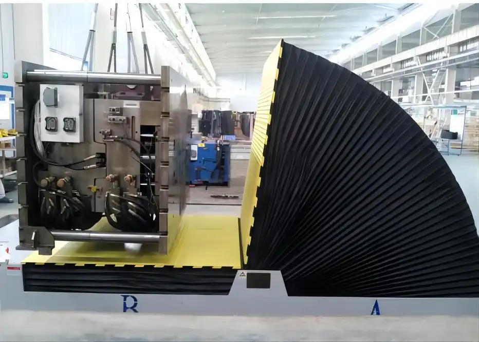
Electrical wiring for industrial mold upenders must comply primarily with the National Electrical Code (NEC/NFPA 70) for the overall installation and NFPA 79 (Electrical Standard for Industrial Machinery) for the machine’s internal wiring and components. Key requirements include proper conductor sizing based on load, robust equipment grounding, appropriate overcurrent protection (fuses/breakers), adherence to specific control circuit wiring practices, and use of industrial-grade components suitable for the operating environment.
Understanding these requirements is crucial for safe, reliable, and compliant operation. This guide breaks down the essential electrical wiring standards, components, and practices specifically for industrial mold upenders, ensuring you navigate the complexities with confidence. Let’s delve into the specifics of the codes and standards governing these powerful machines.
Understanding Key Electrical Codes and Standards
Navigating the web of electrical regulations is fundamental when wiring heavy industrial equipment like mold upenders. These machines involve significant power and unique operational demands, making adherence to safety and performance standards non-negotiable. Key codes like the NEC (NFPA 70), NFPA 79, and OSHA regulations provide the framework for safe electrical design and installation, protecting both personnel and the substantial investment these machines represent. Understanding their specific roles is the first step.
The primary electrical codes governing industrial mold upender wiring are the National Electrical Code (NEC/NFPA 70), NFPA 79 (Electrical Standard for Industrial Machinery), and OSHA standards (specifically 29 CFR 1910 Subpart S). The NEC dictates the overall electrical installation requirements within the facility, including feeder circuits, grounding, and overcurrent protection up to the machine connection point. NFPA 79 specifically addresses the electrical systems within the industrial machinery itself, covering aspects like control circuits, conductor identification (color coding), internal wiring methods, safety interlocks, and components. OSHA enforces workplace safety regulations, ensuring that the final installation and machine operation meet federal safety requirements, referencing both NEC and NFPA standards to ensure a hazard-free environment for employees.
Navigating NEC (NFPA 70) Requirements
The National Electrical Code (NEC), or NFPA 70, serves as the benchmark for safe electrical design, installation, and inspection in the United States. While it applies broadly to premises wiring, specific articles are crucial for connecting industrial machinery like mold upenders.
- Scope and Purpose: The NEC’s primary goal is the "practical safeguarding of persons and property from hazards arising from the use of electricity" (NEC 90.1(A)). It covers installations from the service point down to the outlets and connection points for equipment.
- Feeders and Branch Circuits: Articles 210 (Branch Circuits) and 215 (Feeders) detail requirements for the circuits supplying power to the mold upender. This includes conductor sizing (ampacity based on load, voltage drop considerations), overcurrent protection (circuit breakers or fuses sized appropriately per Article 240), and disconnecting means (Article 430 Part IX for motors, which are typically the main load).
- Grounding and Bonding: Article 250 is paramount. It mandates effective grounding and bonding of electrical equipment, including the frame of the mold upender, raceways, and enclosures. This creates a safe path for fault current, minimizing shock hazards and facilitating the operation of overcurrent devices. An equipment grounding conductor (EGC) is essential for connecting the machine’s non-current-carrying metal parts back to the system ground.
- Wiring Methods: Articles 300-392 cover various wiring methods (conduit, cable trays, etc.). The choice depends on the environment, physical protection needs, and load requirements. For industrial settings, rigid metal conduit (RMC) or intermediate metal conduit (IMC) are often preferred for their durability.
- Equipment Connection: Article 400 covers flexible cords and cables, sometimes used for the final connection if flexibility is needed, subject to limitations. Article 430 (Motors, Motor Circuits, and Controllers) is critical as mold upenders rely heavily on motors. It covers motor circuit conductors, overload protection, control circuits, and disconnects.
Understanding these NEC requirements ensures the infrastructure supplying the mold upender is safe, reliable, and compliant.
| NEC Article | Key Relevance for Mold Upender Installation | Description |
|---|---|---|
| Article 240 | Overcurrent Protection | Specifies requirements for fuses and circuit breakers protecting conductors and equipment. |
| Article 250 | Grounding and Bonding | Details requirements for system grounding and equipment grounding to ensure electrical safety. |
| Article 300 | General Requirements for Wiring Methods and Materials | Covers installation practices, conductor protection, securing/supporting, and raceway fill. |
| Articles 310/Table 310.16 | Conductors for General Wiring / Ampacities | Provides allowable ampacities for insulated conductors based on type, temperature rating, and installation conditions. |
| Article 430 | Motors, Motor Circuits, and Controllers | Crucial for sizing conductors, overload protection, disconnects, and control circuits for the upender’s motors. |
| Article 409 | Industrial Control Panels | Addresses requirements if the upender includes a listed industrial control panel. |
Applying NFPA 79: Electrical Standard for Industrial Machinery
While the NEC governs the building’s wiring up to the machine, NFPA 79 takes over for the electrical system within the industrial machinery itself, including the mold upender. Its purpose is to provide detailed requirements for the electrical equipment of industrial machines to promote safety for personnel, the equipment, and the work process.
Key areas where NFPA 79 specifies requirements often distinct from or more detailed than the NEC include:
- Conductor Identification: NFPA 79 mandates specific color coding for internal wiring (Chapter 13), which differs from typical NEC premises wiring colors. This standardization aids in troubleshooting and maintenance.
- Black: Ungrounded AC/DC power conductors.
- Red: Ungrounded AC control conductors (at less than line voltage).
- Blue: Ungrounded DC control conductors.
- Yellow/Orange: Ungrounded control circuits that remain energized when the main disconnect is off (interlocks, maintenance circuits). NFPA 79 prefers Yellow; IEC 60204-1 uses Orange.
- White or Gray: Grounded AC circuit conductor (neutral).
- White with Blue Stripe: Grounded DC circuit conductor.
- Green or Green with Yellow Stripe(s): Equipment grounding conductor.
- Control Circuits: Chapter 9 details requirements for control circuits, including voltage limitations, protection (often supplementary), and specific rules for safety circuits (e.g., emergency stops).
- Operator Interface & Control Devices: Requirements for pushbuttons, selector switches, indicator lights, and other control devices are outlined (Chapter 10).
- Wiring Practices: Chapter 13 specifies internal wiring practices, such as prohibiting splices outside of enclosures, strain relief for connections, and conductor routing to prevent damage. Raceway fill inside the machine might differ from NEC rules.
- Enclosures and Compartments: Requirements for control panel enclosures (Chapter 11) focus on protection against environmental factors (dust, liquids) relevant to the industrial setting and ensuring adequate access.
- Disconnecting Means: While NEC Article 430 covers motor disconnects, NFPA 79 (Chapter 5) provides specific requirements for the main supply circuit disconnecting means for the entire machine, including handle color (often black or gray, but red/yellow for emergency) and location.
- Protection: Chapter 7 covers overcurrent protection within the machine, often coordinating with the NEC requirements for the branch circuit protection. It also addresses protection against other electrical hazards.
Adherence to NFPA 79 is critical for machine builders and essential for ensuring the mold upender is internally wired for safety, reliability, and ease of maintenance in its industrial environment.
| Conductor Function | NFPA 79 Color Code | IEC 60204-1 Equivalent (Often Relevant) |
|---|---|---|
| Ungrounded AC/DC Power | BLACK | BLACK |
| Ungrounded AC Control (Reduced Voltage) | RED | RED |
| Ungrounded DC Control | BLUE | DARK BLUE |
| Grounded AC Conductor (Neutral) | WHITE or GRAY | LIGHT BLUE |
| Grounded DC Conductor (-) | WHITE with BLUE stripe | WHITE or GRAY |
| Equipment Grounding Conductor | GREEN or GREEN with YELLOW stripe(s) | GREEN-AND-YELLOW |
| Interlock/Energized when Disconnect OFF (Ungrounded) | YELLOW | ORANGE |
| Interlock/Energized when Disconnect OFF (Grounded AC) | WHITE with YELLOW stripe | Not explicitly defined, use base color |
OSHA Regulations: Ensuring Workplace Safety
The Occupational Safety and Health Administration (OSHA) sets and enforces standards to ensure safe and healthful working conditions. For electrical safety, OSHA regulations often incorporate or reference consensus standards like the NEC and NFPA 79. Key OSHA standards relevant to mold upender wiring and operation fall under 29 CFR 1910 (General Industry).
- Subpart S – Electrical: This is the core section for electrical safety.
- 1910.303 (Design Safety Standards): Requires electrical equipment to be listed or labeled by a Nationally Recognized Testing Laboratory (NRTL) and installed according to instructions included in the listing/labeling, essentially mandating compliance with standards like NEC and NFPA 79. Covers aspects like guarding live parts, identification, and suitability for the environment.
- 1910.304 (Wiring Design and Protection): Addresses grounding requirements (mirroring NEC Article 250), overcurrent protection, and wiring methods suitable for the location.
- 1910.305 (Wiring Methods, Components, and Equipment): Details requirements for cabinets, boxes, fittings, conduit, flexible cords, motors, and controllers. It explicitly restricts the use of flexible cords as a substitute for fixed wiring (1910.305(g)(1)(iv)). It also specifies requirements for enclosures in damp or wet locations (1910.305(e)) and motor disconnects being within sight (1910.305(j)(4)).
- 1910.333 (Selection and Use of Work Practices): Focuses on safe work practices when working on or near energized parts, including lockout/tagout (LOTO) procedures (covered more extensively in 1910.147).
- 1910.334 (Use of Equipment): Covers handling portable electric equipment, cord and plug connections, and ensuring equipment is free from recognized hazards.
- 1910.147 (Control of Hazardous Energy – Lockout/Tagout): While not exclusively electrical, LOTO is critical during installation, maintenance, and repair of mold upenders to prevent unexpected energization. Proper electrical disconnects are essential for LOTO procedures.
OSHA’s role is primarily enforcement, ensuring that the installed electrical system and the machine itself, wired according to NEC and NFPA 79, are maintained and operated safely in the workplace. Compliance with OSHA standards is mandatory by law.
Essential Wiring Components and Methods for Mold Upenders
Selecting the right components and using appropriate wiring methods are critical for the performance and safety of industrial mold upenders. These machines handle heavy loads and operate in demanding environments, requiring robust electrical systems. From the conductors carrying the power to the methods used for protection and control, every element plays a vital role in ensuring reliable operation and compliance with stringent safety standards like NFPA 79 and the NEC.
Key electrical components and methods for mold upenders include appropriately sized and insulated conductors (often THHN/THWN in conduit), rigid metal conduit (RMC) or equivalent for physical protection, listed industrial control panels housing motor starters and controllers, correctly rated circuit breakers or fuses for overcurrent protection, effective equipment grounding conductors (EGCs), properly installed disconnect switches, and durable control devices (pushbuttons, sensors) wired according to NFPA 79 color codes and practices.
Conductor Selection and Sizing
Choosing the correct conductors (wires) is fundamental. Several factors influence this decision:
- Ampacity: The conductor must safely carry the expected maximum current without overheating. This is determined based on the motor’s Full Load Current (FLC) rating (from NEC Table 430.250 for standard motors or nameplate for specific motors), plus any control circuit or auxiliary loads. NEC Article 310, particularly Table 310.16, provides ampacities for various conductor types, sizes, and insulation ratings under specific conditions (e.g., ambient temperature, number of current-carrying conductors in a raceway). For motor circuits, NEC 430.22 requires conductors supplying a single motor to have an ampacity of at least 125% of the motor FLC.
- Insulation Type: The insulation must be suitable for the voltage, temperature, and environmental conditions (e.g., moisture, oil, chemicals). Common types used in industrial conduit installations include THHN (Thermoplastic High Heat-resistant Nylon-coated) for dry/damp locations and THWN (Thermoplastic Heat- and Water-resistant Nylon-coated) for wet locations. NFPA 79 may specify particular insulation types for internal machine wiring.
- Voltage Drop: For longer runs, the voltage drop across the conductor must be considered. Excessive voltage drop can impair motor performance and efficiency. NEC informational notes suggest limiting voltage drop to 3% for branch circuits and 5% total for feeders and branch circuits combined. Calculation involves conductor length, current, and conductor resistance (found in NEC Chapter 9, Table 8). Larger conductor sizes may be needed to mitigate voltage drop than what ampacity alone requires.
- Material: Copper is the standard due to its excellent conductivity. Aluminum is lighter and less expensive but requires larger sizes for the same ampacity and specific termination techniques.
- Color Coding: Adherence to NEC (for facility wiring) and NFPA 79 (for machine wiring) color codes is mandatory for identification and safety.
Proper selection ensures conductors operate safely, efficiently, and reliably throughout the machine’s lifespan.
Grounding and Bonding: The Safety Backbone
Effective grounding and bonding are arguably the most critical safety aspects of any electrical installation, especially for heavy machinery like mold upenders.
- Purpose: Grounding provides a path for fault current to return to the source, enabling overcurrent devices (breakers/fuses) to operate quickly and clear the fault. This minimizes the risk of electric shock if non-current-carrying metal parts become energized and reduces fire hazards. Bonding ensures that all metallic components are at the same electrical potential, preventing dangerous voltage differences between them.
- Equipment Grounding Conductor (EGC): This is the conductor that connects the metal frame of the mold upender, motor casings, control panels, and raceways back to the grounding terminal bus in the panelboard, which is ultimately connected to the system ground (grounding electrode). The EGC must be sized according to NEC Table 250.122 based on the rating of the circuit’s overcurrent protective device. It can be bare, covered, or insulated (green or green/yellow stripe). Often run within the same raceway as the power conductors.
- Bonding Jumpers: Used to ensure electrical continuity across connections that might otherwise be interrupted (e.g., connecting conduit sections, bonding enclosures). NEC Article 250 Part V covers bonding requirements.
- Methods: Grounding connections must be mechanically and electrically secure, often using listed lugs, pressure connectors, or screws specifically designed for grounding. Surface preparation (removing paint/coatings) might be necessary to ensure good contact. Metal raceways (like RMC) can sometimes serve as the EGC under specific conditions (NEC 250.118), but often a separate wire-type EGC is run for enhanced reliability, especially in industrial settings. NFPA 79 also emphasizes robust grounding within the machine’s structure and control panels.
Failure to properly ground and bond can render overcurrent protection ineffective and create severe shock hazards.
Overcurrent Protection: Safeguarding Equipment and Personnel
Overcurrent protection devices (OCPDs), such as circuit breakers and fuses, are essential for protecting conductors and equipment from damage due to overloads (excess current) and short circuits (high-magnitude fault currents).
- Purpose: OCPDs interrupt the flow of electricity when current exceeds a predetermined safe level. This prevents wires from overheating (fire hazard) and protects motors and control components from destructive currents.
- Types:
- Circuit Breakers: Reusable devices that trip open when an overcurrent is detected. Molded Case Circuit Breakers (MCCBs) are common in industrial panels. They offer both thermal (overload) and magnetic (short circuit) protection.
- Fuses: Single-use devices containing a filament that melts and breaks the circuit during an overcurrent event. Different types exist (e.g., time-delay fuses are often used for motor circuits to handle temporary starting currents).
- Sizing:
- Short Circuit and Ground Fault Protection: Governed by NEC Article 240 and Article 430 Part IV. The OCPD must protect the branch circuit conductors. For motor circuits, NEC 430.52 allows sizing the OCPD significantly higher than the motor FLC (up to 250% for inverse-time breakers, or even higher for instantaneous trip breakers or fuses, per Table 430.52) to allow the motor to start without tripping.
- Overload Protection: Specifically protects the motor from sustained overcurrents due to excessive load. This is typically provided by a separate overload relay, often integrated into the motor starter (NEC Article 430 Part III). Overload relays are sized closer to the motor FLC (typically 115-125% of nameplate Service Factor Amps or FLC).
- Coordination: In complex systems, OCPDs might be coordinated so that the device closest to the fault trips first, minimizing the impact on the rest of the system.
- Location: OCPDs are typically located in panelboards or switchgear where the circuit originates.
Choosing and correctly sizing OCPDs according to NEC and manufacturer specifications is crucial for both safety and operational reliability.
Control Circuit Wiring: Precision and Reliability
The control circuits manage the operation of the mold upender – starting, stopping, tilting, safety interlocks, etc. While typically lower voltage (e.g., 120VAC or 24VDC), their wiring requires precision and adherence to specific standards, primarily NFPA 79.
- Voltage: Control circuits often operate at a lower voltage than the main power circuit, derived from a control transformer or DC power supply. This enhances safety for operators interacting with control devices.
- Protection: Control circuits require their own overcurrent protection, typically supplementary fuses or circuit breakers sized appropriately for the control transformer and wiring (NFPA 79 Chapter 7 & 9). Grounding of control circuits follows specific rules depending on the configuration (NFPA 79 Chapter 8).
- Conductor Identification (Color Coding): Strict adherence to NFPA 79 color codes (Blue for DC control, Red for AC control, Yellow/Orange for interlocks energized when main disconnect is off) is essential for troubleshooting and safety.
- Wiring Methods: Conductors are typically run within the control panel enclosure, often in wire duct (panduit). Connections should be made using reliable terminals (e.g., screw terminals with ferrules on stranded wire) ensuring secure connections. Strain relief is important where wires connect to moving parts or devices.
- Safety Circuits: Wiring for emergency stops (E-stops) and safety interlocks must follow specific safety standards (e.g., IEC 60204-1, ISO 13849-1). This often involves redundant wiring, specific safety relays or safety PLCs, and fail-safe principles. NFPA 79 addresses basic safety circuit requirements.
- PLC/Sensor Wiring: If the mold upender uses a Programmable Logic Controller (PLC), specific wiring practices for inputs (sensors, limit switches) and outputs (solenoids, starter coils) apply, often dictated by the PLC manufacturer and requiring careful shielding for analog signals or high-speed communication lines to prevent noise interference.
Reliable and properly documented control circuit wiring is key to the mold upender’s functionality and safe operation.
Power Supply Planning and Installation Considerations
Planning the power supply for an industrial mold upender involves more than just running a cable. Inadequate planning can lead to voltage issues, nuisance tripping, insufficient power, and safety hazards. A systematic approach is needed to ensure the electrical supply reliably meets the machine’s demands throughout its operational cycle, considering peak loads and environmental conditions.
Effective power supply planning for a mold upender requires calculating the total electrical load (motors, controls, heaters), determining the correct voltage and phase requirements based on the machine’s specifications, selecting appropriate circuit protection (breakers/fuses), and choosing suitable wiring methods (conduit type, conductor size considering voltage drop) and disconnect means compliant with NEC and OSHA regulations for the specific installation environment.
Calculating Power Requirements
Accurately determining the total power demand is the foundation of supply planning. This involves summing the requirements of all electrical components:
- Motors: The primary load. Obtain the Full Load Amperes (FLA) or Horsepower (HP)/Kilowatts (kW) rating from the motor nameplate(s). If only HP is given, use NEC Table 430.250 (for 3-phase AC motors) to find the corresponding FLA for the system voltage. Remember that starting current (Locked Rotor Amperes or LRA) can be 5-7 times the FLA, influencing breaker selection but not typically conductor sizing (which uses 125% FLA per NEC 430.22).
- Control Systems: Include the load of control transformers, PLCs, power supplies (e.g., 24VDC supplies), and any significant control devices. This is usually specified in Volt-Amperes (VA) or Watts (W).
- Auxiliary Components: Consider heaters (if used for hydraulic reservoirs), cooling fans, lighting within the machine, and any other electrically powered accessories.
- Duty Cycle: Is the operation continuous or intermittent? While conductors are sized for continuous load (or based on NEC rules for intermittent duty if applicable), the overall demand factor might influence feeder sizing if multiple machines share a supply.
- Total Load Calculation: Convert all loads to Amperes at the supply voltage. Sum the FLA of all motors (adjusting for duty cycle if appropriate per NEC Article 430 Part II) and add the current draw of control systems and auxiliary components. For sizing feeders supplying multiple motors or motor(s) and other loads, NEC 430.24 requires sizing the feeder conductor ampacity to be at least 125% of the largest motor’s FLA plus the sum of the FLAs of all other motors and other loads on the feeder.
An accurate load calculation prevents undersized supplies, voltage sags, and overheating.
| Component Example | Rating Example | Calculation Step | Estimated Amps @ 480V 3Ø |
|---|---|---|---|
| Main Hydraulic Motor | 20 HP | FLA from NEC T430.250 ≈ 27A | 27 A |
| Tilt Motor | 5 HP | FLA from NEC T430.250 ≈ 7.6A | 7.6 A |
| Control Transformer | 500 VA (0.5 kVA) | Amps = VA / (Voltage √3) = 500 / (480 1.732) | 0.6 A |
| PLC & I/O Power Supply | 100 W (assume PF=1) | Amps = Watts / (Voltage √3) = 100 / (4801.732) | 0.12 A |
| Feeder Sizing Basis | 125% * Largest Motor FLA + Sum of Other Loads | 1.25 * 27A + 7.6A + 0.6A + 0.12A = 42.07 A | |
| Conductor Ampacity Req. | Must be ≥ 42.07 A | (Select conductor per NEC 310.16) |
Note: This is a simplified example. Actual calculations must consider specific nameplate data, temperature derating, and conductor bundling per NEC.
Voltage and Phase Requirements
Industrial machinery typically operates on specific voltage and phase systems. Ensuring compatibility is crucial:
- Common Industrial Systems: In the US, 480V 3-phase is very common for industrial motors due to efficiency over long distances and smaller conductor sizes compared to lower voltages. 240V 3-phase or single-phase might be used for smaller machines. 600V 3-phase is prevalent in Canada. Control circuits are often stepped down to 120V single-phase or 24VDC.
- Machine Specifications: Always verify the required voltage, phase, and frequency (Hz) from the mold upender’s documentation or nameplate. Mismatched voltage can severely damage equipment or prevent operation.
- Transformers: If the facility’s supply voltage doesn’t match the machine’s requirement, a transformer (step-up or step-down) will be necessary. This adds complexity and requires its own protection and sizing considerations per NEC Article 450.
- Phase Converters: If only single-phase power is available but the machine requires 3-phase, a phase converter (rotary or static) might be an option, but these have limitations and potential impacts on motor performance and must be carefully evaluated.
Confirming voltage and phase compatibility early in the planning process avoids costly errors and delays.
Installation Best Practices
Proper installation techniques ensure the longevity, safety, and compliance of the electrical supply.
- Raceways and Cable Management: Conductors must be protected from physical damage.
- Conduit: Rigid Metal Conduit (RMC) or Intermediate Metal Conduit (IMC) provide the best physical protection in demanding industrial environments. Electrical Metallic Tubing (EMT) may be acceptable in less harsh areas but offers less protection. Liquidtight Flexible Metal Conduit (LFMC) or Liquidtight Flexible Nonmetallic Conduit (LFNC) might be needed for connections to motors or components requiring vibration isolation or minor movement, but their use is subject to NEC and NFPA 79 limitations.
- Cable Trays: Permitted by NEC Article 392 in some industrial settings, allowing for easier routing of multiple cables, but specific cable types must be used (e.g., Type TC – Tray Cable).
- Securing and Support: Raceways and cables must be securely fastened and supported at intervals specified by the NEC (e.g., NEC 344.30 for RMC).
- Environmental Considerations:
- Damp/Wet Locations: Enclosures (panelboards, junction boxes, disconnects) must be rated appropriately (e.g., NEMA 3R, 4, or 4X) to prevent water ingress (NEC 110.28, 430.10(A), OSHA 1910.305(e)). Wiring methods must also be suitable (e.g., THWN conductors, watertight fittings). A minimum 1/4-inch airspace is often required behind enclosures mounted on surfaces in wet locations (NEC 312.2).
- Hazardous Locations: If the area is classified due to flammable gases, dust, or fibers, specialized wiring methods and explosion-proof enclosures are mandatory per NEC Articles 500-505.
- Disconnecting Means: A readily accessible disconnect switch is required for the machine, capable of isolating all ungrounded conductors. Per NEC 430.102 and OSHA 1910.305(j)(4), the motor controller disconnect must generally be within sight of the controller, and the motor disconnect within sight of the motor. NFPA 79 requires a main supply disconnect for the entire machine. Locks must be available for LOTO procedures.
- Terminations: Connections must be made using listed connectors suitable for the conductor type and size. Torque specifications for terminal lugs should be followed to ensure secure, low-resistance connections.
Following these best practices ensures a safe, durable, and compliant installation.
Safety First: Wiring Practices to Prevent Hazards
Beyond basic code compliance, prioritizing safety during the electrical installation and maintenance of industrial mold upenders is paramount. These machines involve high power levels and heavy moving parts, creating significant potential hazards if electrical safety is compromised. Implementing robust safety practices protects personnel from shock, burns, arc flash, and prevents fires or equipment damage. Adherence to established safety protocols is not just good practice; it’s often a legal requirement enforced by OSHA.
Critical safety practices for mold upender wiring include strict adherence to Lockout/Tagout (LOTO) procedures during any work, ensuring proper installation and function of emergency stop (E-stop) circuits per NFPA 79 and relevant safety standards, using appropriate Personal Protective Equipment (PPE) based on arc flash hazard analysis (NFPA 70E), conducting regular inspections and maintenance of wiring systems, and ensuring only qualified electricians perform installation and repair tasks.
Implementing Lockout/Tagout (LOTO) procedures (OSHA 1910.147) before any installation, maintenance, or repair work is non-negotiable. This involves de-energizing the equipment, isolating it from the power source using the main disconnect switch, locking the switch in the off position, and tagging it to indicate work is in progress. Verifying the absence of voltage before touching any conductors is a critical step.
Emergency stop (E-stop) circuits must be designed and wired according to safety standards (NFPA 79, ISO 13849-1). E-stops should be readily accessible, easily identifiable (red mushroom head on a yellow background), and function reliably to bring the machine to a safe state in an emergency. Their wiring often involves safety relays or safety PLCs to ensure high reliability.
Working on or near energized equipment requires specific precautions outlined in NFPA 70E (Standard for Electrical Safety in the Workplace). This includes performing an arc flash hazard analysis to determine the potential incident energy, establishing protection boundaries, and requiring workers to wear appropriate arc-rated PPE (clothing, face shields, gloves). However, the safest approach is always to de-energize equipment before working on it (LOTO).
Regular inspections and preventative maintenance are crucial. This includes checking for damaged insulation, loose connections, signs of overheating, proper grounding continuity, and ensuring enclosures are secure and environmental seals are intact. Infrared thermography can help identify potential issues like hot spots before they cause failures.
Finally, only qualified electricians, defined by OSHA (1910.399) as those with the skills, knowledge, and safety training related to the construction and operation of electrical equipment and installations, should perform electrical work. They understand the hazards involved, the relevant codes (NEC, NFPA 79), and the necessary safety precautions. Proper documentation, including updated electrical drawings and schematics, is also vital for ongoing safety and maintenance.
Conclusion
Ensuring the correct electrical wiring for industrial mold upenders is crucial for operational efficiency, equipment longevity, and, most importantly, personnel safety. Compliance involves navigating a complex landscape of standards, primarily the NEC (NFPA 70) for facility wiring, NFPA 79 for the machine’s internal electrical system, and OSHA regulations for overall workplace safety. Key considerations include accurate power requirement calculations, proper conductor sizing and selection, robust grounding and bonding, correctly rated overcurrent protection, adherence to specific control circuit wiring practices (including color coding), and installing components suitable for the industrial environment. Understanding the nuances of Industrial electricity requirements, combined with rigorous adherence to safety protocols like LOTO and the use of qualified personnel, guarantees a safe and reliable installation.


