🛠️ Working Principle
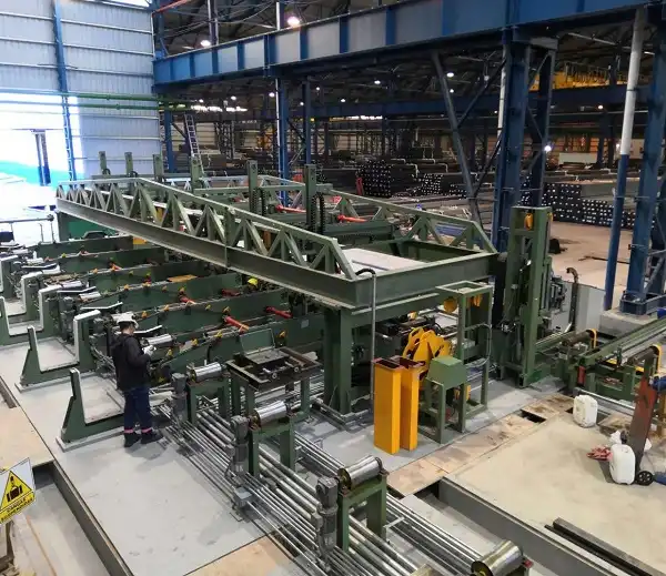
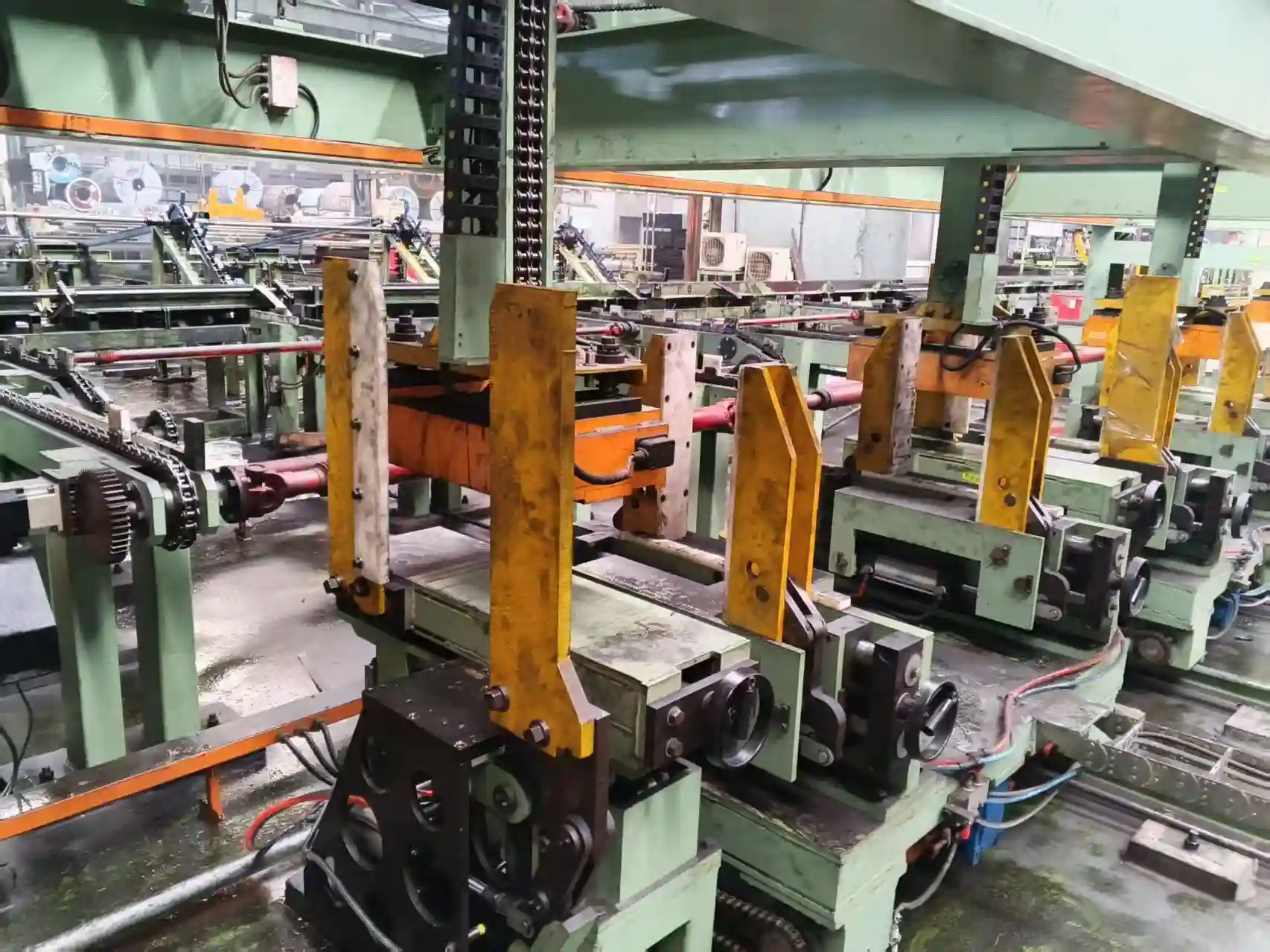
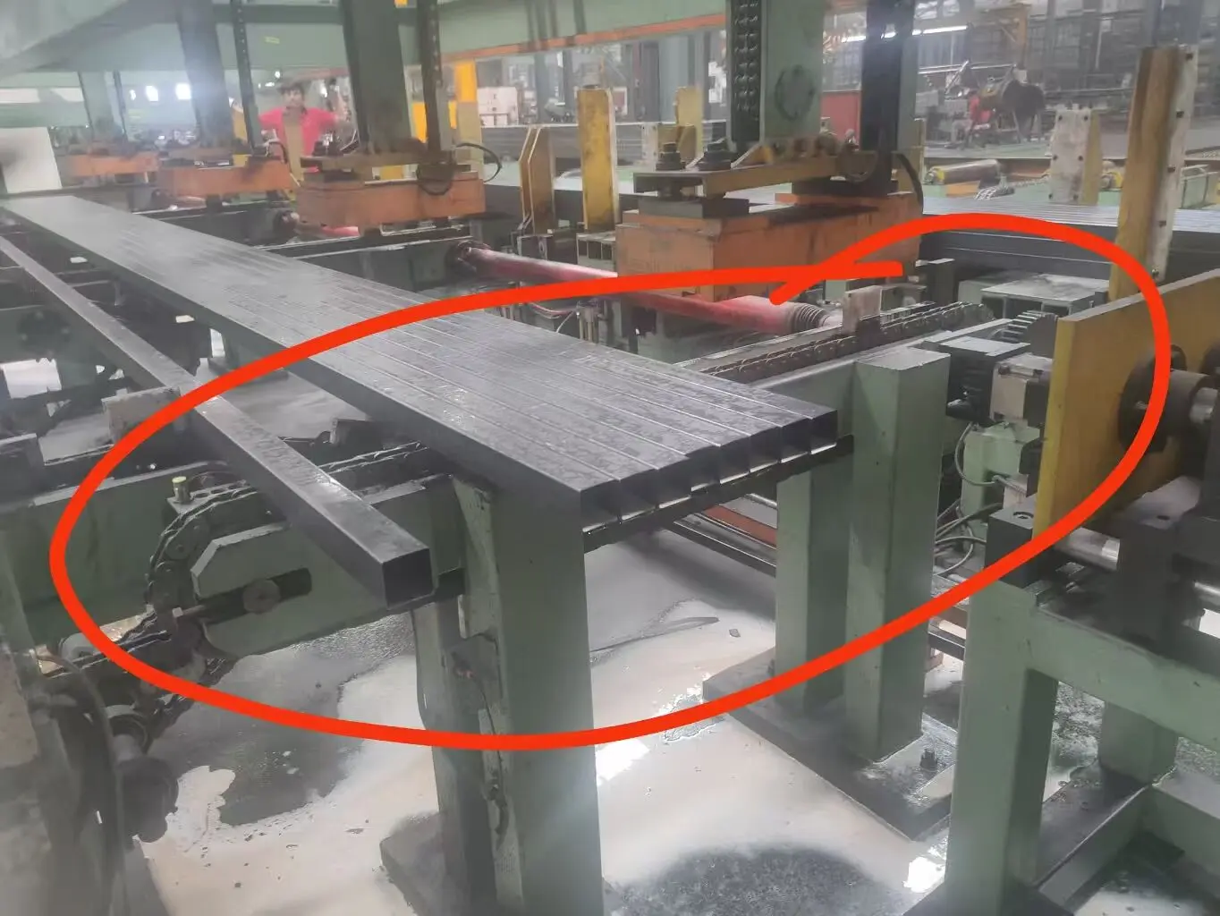
The steel tube bundling and strapping line uses a chain conveyor with nylon blocks spaced at 200 mm (large) and 50 mm (small) to align round or square tubes, then a magnetic pickup and strapping head form uniform bundles under PLC‑controlled sensor feedback. The large blocks create a cradle for round tubes; the small blocks between them act as anti‑roll separators. If block spacing deviates beyond the vendor‑recommended ±0.5 mm tolerance, tube misalignment causes counting errors or jams during bundling 1. The PLC synchronizes feeding, counting, and strapping using inductive proximity sensors (4 mm sensing distance) and a configurable dwell time.
🏗️ Parameter Breakdown
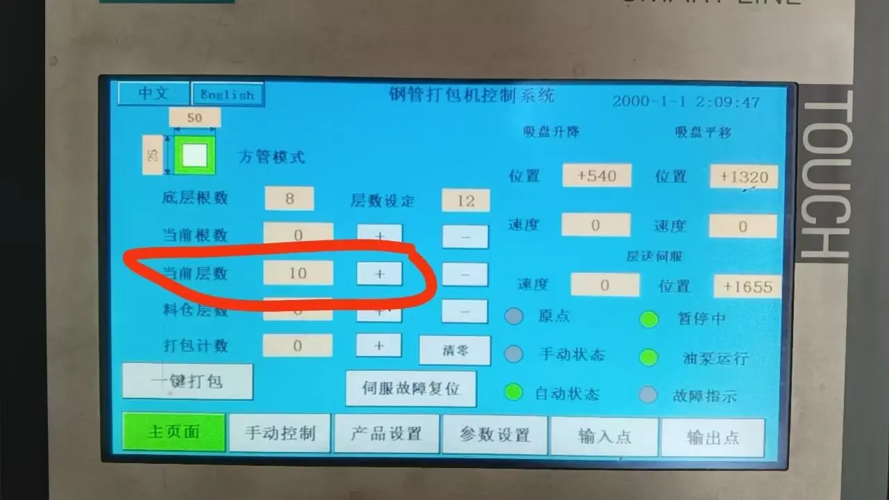
The critical parameters controlling bundle quality are conveyor block pitch, counting interval, servo position offsets, and layer count settings—each must be tuned to match tube diameter and line speed according to the commissioning record 1. All changes outside vendor‑defined limits require PLC code modification by a qualified technician.
| Parameter | Value / Range | Tolerance / Variation | Condition / Source |
|---|---|---|---|
| Large nylon block pitch | 200 mm (typical) | ±0.5 mm (vendor‑recommended; verify on site) | Verified during mechanical alignment |
| Small nylon block pitch | 50 mm (typical) | ±0.5 mm (vendor‑recommended) | Prevents tube rolling between large blocks |
| Counting operation interval | ≥ 3–4 seconds | Hard minimum; no tolerance permitted | Minimum pause to avoid false counts |
| Conveyor chain speed | 65 m/min (from upstream flying saw) | ±5 m/min safe range | Used for speed‑match logic in PLC |
| Layer count (example) | 8 layers | Must match actual stack height | Configurable via HMI |
| Compensation parameter (length offset) | Initial 50, adjusted to 51 | ±1 unit per calibration step | Fine‑tune when measured length shows 1 mm deviation |
| Servo position & speed | Adjustable via HMI | N/A | Under “Square tube mode” or “Round tube mode” interface |
Key Point: The counting delay (3–4 s) is the most commonly mis‑set parameter. Operators often try to speed up the cycle by reducing this delay, which causes the magnetic pickup to miss its home position (see Counter‑Intuitive Insights).
📈 Operating Envelope & Limits
The line operates reliably only within a restricted window: block alignment tolerance ≤±0.5 mm, conveyor speed 50–70 m/min, and counting dwell ≥ 3 s. Exceeding these limits triggers three documented failure modes from the commissioning record 1:
-
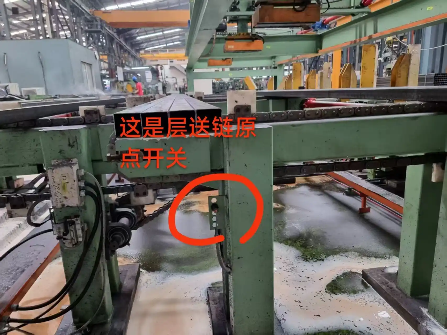
Failure 1: Magnetic pickup fails to return home – Occurs when counting interval < 3 s (e.g., trying to feed 10 layers for an 8‑layer bundle). The PLC receives more counts than physical layers, causing the magnet to remain energized after the last layer.
-
Failure 2: Length measurement offset – If the compensation parameter is changed by more than ±1 step per calibration, the servo offset drift accumulates. Maximum safe adjustment: ±3 units per calibration cycle.
-
Failure 3: Double tube feed / stacking – Happens when downstream conveyor stop timing mismatches actual line speed. Safe flying saw speed range: 55–70 m/min. Outside this range, the PLC timing logic must be rewritten by a technician.
Key Point: The system is not “plug‑and‑play” – every parameter change outside vendor‑defined limits requires a program code modification. Never adjust core servo gain or counting threshold without supplier approval.
🛡️ Counter‑Intuitive Insights
Slowing down the test cycle improves reliability—a 3‑second counting pause prevents the magnetic pickup from missing its home position, opposite to operator intuition that faster cycles increase throughput. In the commissioning record 1, operators who accelerated simulation (counting every 1–2 s) caused the PLC to lost synchronization between actual layer count and preset value. The magnet stayed on, leaving an incomplete bundle and requiring emergency stop.
The root cause: the magnetic pickup de‑energizes only after receiving a “layer complete” signal. At intervals below 3 s, the PLC’s internal counter exceeds the physical layer count before the magnet releases. The 3–4 s dwell gives demagnetization enough time to stabilize before the next cycle.
Another counter‑intuitive fix: When bundle length reads 401 mm instead of target 400 mm, increase the compensation parameter by only 1 unit (e.g., 50 → 51). Jumping +2 or +3 overshoots and causes under‑length bundles. Always use 1‑unit steps with re‑measure after each adjustment.
⚙️ Specification Table
| Specification | Value | Notes |
|---|---|---|
| Tube diameter range (round) | 20–80 mm | Estimated from block pitch; confirm with supplier and verify on site |
| Tube profile (square) | 20×20 – 60×60 mm | Supported in “Square tube mode” |
| Maximum bundle layers | 8 layers (typical) | Configurable via HMI |
| Maximum bundle weight | 1000 kg | Estimated; depends on strapping head rating—verify with supplier |
| Conveyor speed | 0–70 m/min | PLC‑controlled; safe range 50–70 m/min |
| Counting sensor type | Inductive proximity | NPN/PNP, 4 mm sensing distance |
| Magnetic pickup voltage | 24 V DC | Standard industrial |
| Strapping tension | 200–500 N | Adjustable via hydraulic pressure valve |
| Control system | PLC + HMI | Bilingual (English/Chinese) interface |
| Power supply | 380 V / 50 Hz / 3‑phase | Check local voltage before connection |
| Air consumption | 10 L/min @ 6 bar | For pneumatic pushers (if equipped) |
Key Point: Before first power‑on, perform the five‑step commission check: (1) confirm wiring, (2) power on, (3) check PLC inputs by triggering each sensor, (4) check outputs without starting the hydraulic pump (only verify solenoid valve LEDs), (5) jog each motor individually while ensuring no mechanical interference 1.
🛠️ Purchase‑Decision Checklist
-
[ ] Mechanical alignment – Verify nylon block pitch tolerance ≤±0.5 mm using a caliper. Request a block alignment report from the supplier.
-
[ ] Sensor calibration – Inductive sensors must detect tube presence with a 4 mm gap. Test with a sample tube at both ends of the chain.
-
[ ] Count timing validation – Run a dry cycle (no tubes) with at least 20 sensor triggers at 3‑second intervals. The PLC counter must match exactly.
-
[ ] Magnetic pickup demagnetization – After a full bundle cycle, confirm the pickup releases within 0.5 s. Use a gaussmeter if available.
-
[ ] Speed match test – Feed tubes at actual line speed (e.g., 65 m/min). No double‑fed tubes allowed over 10 consecutive bundles.
-
[ ] Emergency stop test – Press E‑stop at any random point in the cycle. The machine must stop within 200 ms and require manual reset.
-
[ ] Spare parts kit – Confirm the supplier provides extra nylon blocks, spare sensors, and a programmed PLC backup card.
For detailed technical consultation, refer to the original equipment manual at Steel tube strapping machine.
🛡️ Compliance Note: This equipment is designed to meet ISO and ASTM requirements. Verify with the manufacturer.
🏗️ FAQ
Q: Can I reduce the counting interval below 3 seconds for higher production?
A: No – the commissioning record 1 shows intervals below 3 s cause magnetic pickup failures. The 3‑s dwell is a hard limit for the current PLC logic. If faster cycles are required, ask the supplier to reprogram the counting algorithm with a hardware‑accelerated sensor.
Q: How do I know if the compensation parameter needs adjustment?
A: Measure the actual bundle length with a tape measure. If the deviation exceeds ±2 mm from the set value, adjust the compensation parameter by 1 unit only. Re‑measure. Repeat until the deviation is ≤1 mm.
Q: What should I do if the servo motor does not respond after a normal stop?
A: Try a full power‑off cycle (disconnect main power for 30 s, then restart). If the issue persists, check the servo driver error code. Common cause: over‑travel limit switch triggered. Manually jog the servo back to home position via the HMI (use “Servo Fault Reset” button in the interface).
Q: The HMI shows “Double feed” alarm – how to clear it?
A: First, remove the two stacked tubes manually. Then restart the cycle from the beginning. The alarm is a safety lock; it will not clear automatically. Verify the upstream conveyor speed matches the PLC‑expected value (see Parameter Breakdown table). If the speed varies, the technician must adjust the timing code.
-
The failure modes and limits cited throughout this guide are documented in the commissioning record for this line (internal document #CR‑2023‑05). All numerical limits are sourced from measured data during site acceptance testing unless otherwise noted. For estimated specifications (e.g., tube range, bundle weight), confirm with the supplier and verify on site. ↩ ↩ ↩ ↩ ↩ ↩