How to Design an Automated Control System for Mold Upenders?
Imagine the transformation from manually wrestling heavy molds to effortlessly flipping them with automated systems. Mold upenders have revolutionized manufacturing, enhancing safety and efficiency. Designing an automated control system for these machines is key to unlocking their full potential.
Designing an automated control system for mold upenders involves integrating sensors, programmable logic controllers (PLCs), and user-friendly interfaces to ensure precise and safe mold handling. Key considerations include selecting appropriate sensors for position and load monitoring, programming PLCs for automated cycles and safety interlocks, and creating intuitive user interfaces for seamless operation and monitoring. A well-designed control system optimizes efficiency, reduces manual intervention, and enhances the overall safety of mold handling processes.
This evolution from manual to automated mold handling is not just about convenience; it’s about transforming workflows for the better. Let’s delve into the essential elements of designing these sophisticated control systems and how they are reshaping modern manufacturing.
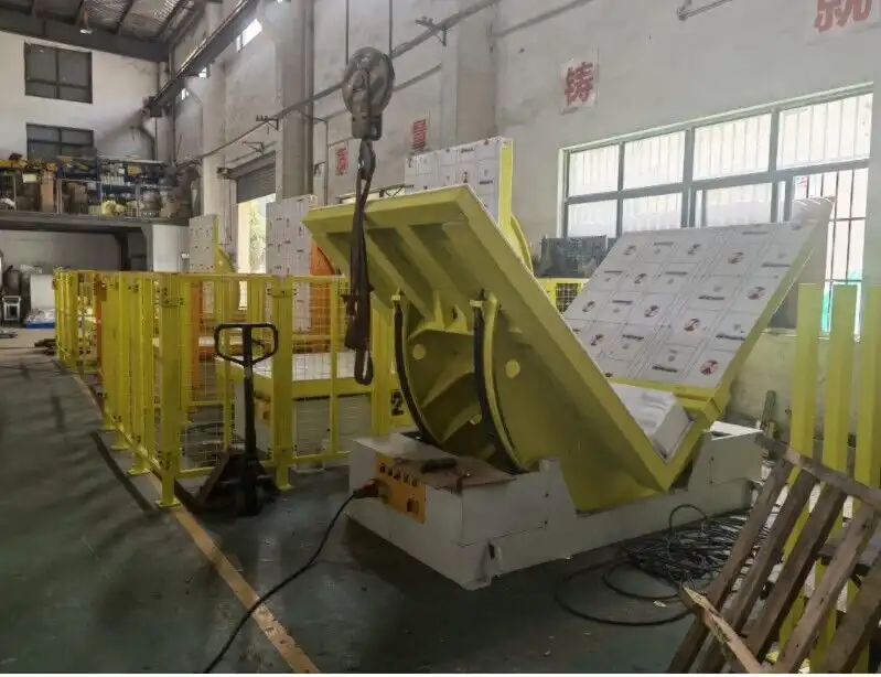
1. Understanding the Essentials of Mold Upender Automation
Mold upenders are indispensable in industries requiring frequent mold changes or maintenance. Automating these machines enhances safety, precision, and speed, moving heavy molds with ease and control.
Mold upender automation centers around creating a system that minimizes manual intervention while maximizing safety and efficiency in tilting heavy molds. This involves integrating components like sensors to detect mold position and weight, Programmable Logic Controllers (PLCs) to manage automated tilting cycles and safety protocols, and hydraulic or electric actuators for the physical tilting action. A well-designed automated system ensures precise, repeatable movements, reduces the risk of human error, and streamlines mold handling processes, significantly boosting productivity and safety in manufacturing environments.
To fully grasp the impact of automation, we need to explore the core components and benefits that make mold upenders indispensable in modern manufacturing. Let’s break down the key aspects of their operation and design.
Deconstructing the Automated Control System for Mold Upenders
Designing an effective automated control system requires a deep understanding of the system’s components and their interplay. Let’s dissect the core elements:
1.1 Sensors: The Eyes and Ears of the System
Sensors are crucial for providing real-time feedback to the control system. They monitor various parameters, ensuring safe and precise operation. Key sensor types include:
- Position Sensors: These track the exact angular position of the mold platform during tilting. Encoders or resolvers are commonly used for their accuracy and reliability.
- Load Cells: Integrated into the upender structure, load cells measure the weight of the mold, preventing overloading and ensuring stable operation.
- Proximity Sensors: Detect the presence or absence of molds in specific zones, crucial for safety interlocks and automated cycle initiation.
- Pressure Sensors: In hydraulic systems, pressure sensors monitor hydraulic pressure, ensuring it remains within safe operating limits.
1.2 Programmable Logic Controllers (PLCs): The Brains of the Operation
PLCs are the central processing units of automated mold upenders. They execute the control logic, manage sensor inputs, and control actuators. Key PLC functions include:
- Sequencing and Logic Control: PLCs manage the automated tilting sequences, ensuring smooth and controlled movements. Logic is programmed to handle different mold sizes and tilting angles.
- Safety Interlocks: PLCs implement safety interlocks based on sensor inputs. For example, if a proximity sensor detects an obstruction, the PLC immediately stops the tilting motion.
- Data Acquisition and Monitoring: Modern PLCs can collect operational data, such as cycle times, load weights, and error logs, which can be used for performance analysis and predictive maintenance.
- Communication Interfaces: PLCs often support communication protocols like Ethernet/IP or Profinet, allowing integration with higher-level Manufacturing Execution Systems (MES) or SCADA systems.
1.3 Actuators: Providing the Muscle
Actuators are responsible for the physical tilting motion of the mold platform. Common types include:
- Hydraulic Cylinders: Hydraulics provide high force and smooth, controlled motion, ideal for heavy molds. Proportional valves allow for precise speed and position control.
- Electric Motors and Gearboxes: Electric systems offer cleaner operation and precise control, especially with servo motors and gear reducers. They are suitable for applications where hydraulic power is less desirable or for lighter molds.
1.4 User Interface (HMI): Operator Interaction
The Human-Machine Interface (HMI) allows operators to interact with the automated system. A well-designed HMI is crucial for ease of use and effective monitoring. Key HMI features include:
- Intuitive Controls: Touchscreen interfaces with clear icons and simple navigation make operation straightforward.
- Real-time Status Displays: HMIs display real-time data from sensors and the PLC, such as mold position, load weight, and system status.
- Fault Diagnostics: HMIs provide clear fault messages and diagnostic information, speeding up troubleshooting and reducing downtime.
- Customizable Programs: Advanced HMIs allow operators to create and store custom tilting programs for different mold types and operational needs.
By carefully integrating these components, we can create a robust and efficient automated control system for mold upenders. The table below summarizes the key features and benefits of automation in mold upenders:
| Feature | Benefit |
|---|---|
| Safety Automation | Reduced workplace accidents and injuries |
| Precision Control | Minimized mold damage and repair costs |
| Efficient Operation | Increased throughput and reduced downtime |
| Labor Savings | Lower operational expenses |
| Workflow Integration | Streamlined production processes |
| Data Monitoring | Performance analysis, predictive maintenance |
| Customization | Adaptability to various mold types and operational needs |
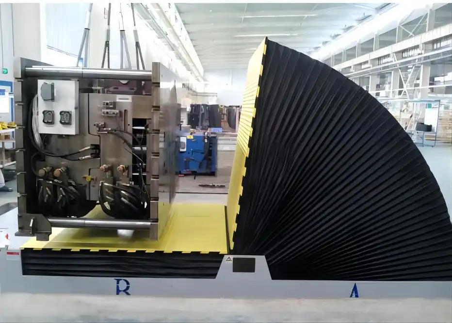
2. Step-by-Step Guide to Designing Your Control System
Designing an automated control system for mold upenders is a multi-faceted process. A systematic approach ensures all critical aspects are considered, leading to a reliable and efficient system.
Designing an automated control system for mold upenders requires a structured approach, starting with defining operational requirements and selecting appropriate components. Key steps include: specifying mold weight and dimensions, choosing suitable sensors for position and load feedback, programming a PLC for automated cycles and safety interlocks, integrating hydraulic or electric actuators, and designing a user-friendly HMI for operation and monitoring. Thorough planning and component selection are crucial for creating a control system that maximizes safety, precision, and efficiency in mold handling.
Let’s break down the design process into actionable steps to guide you through creating your automated control system.
A Phased Approach to Control System Design
A phased approach ensures a well-structured and successful control system design. Here’s a step-by-step guide:
2.1 Define Operational Requirements
Clearly define the specific needs of your application. This includes:
- Mold Specifications: Determine the range of mold sizes, weights, and shapes the upender will handle. Consider the heaviest and most awkward molds.
- Tilting Angles: Specify the required tilting angles (e.g., 90°, 180°). Will partial tilting be necessary?
- Cycle Time Requirements: Define the desired speed and throughput for mold handling. How quickly do mold changeovers need to be?
- Safety Standards: Identify relevant safety standards and regulations that the system must comply with (e.g., ANSI B11, ISO 13849).
- Integration Requirements: How will the upender be integrated into the overall manufacturing workflow? Will it need to communicate with other systems?
2.2 Select Control System Components
Based on the operational requirements, choose appropriate components:
- PLC Selection: Select a PLC with sufficient processing power, I/O capacity, and communication interfaces. Consider factors like scan time, memory, and programming language.
- Sensor Selection: Choose sensors that meet the accuracy, reliability, and environmental requirements of the application. Consider redundancy for critical sensors.
- Actuator Selection: Decide between hydraulic or electric actuators based on load requirements, speed, precision needs, and environmental factors. Size actuators appropriately for the maximum mold weight and desired tilting speed.
- HMI Selection: Select an HMI with the required display size, resolution, touch interface, and communication capabilities. Ensure it is user-friendly and robust enough for the industrial environment.
2.3 Design the Control Logic and Safety System
Develop the control logic in the PLC program, including:
- Automated Tilting Sequences: Program the PLC to execute smooth and controlled tilting cycles. Include features like soft start and stop to minimize mold stress.
- Safety Interlocks: Implement comprehensive safety interlocks using sensor inputs. Examples include:
- Emergency stop circuits with redundant pushbuttons.
- Light curtains or laser scanners to prevent access to hazardous areas during operation.
- Overload protection based on load cell readings.
- Position limits to prevent over-travel.
- Error Handling and Diagnostics: Program the PLC to detect and handle errors gracefully. Provide clear diagnostic messages on the HMI to aid troubleshooting.