The Single-Operator Steel Pipe Facility: A Blueprint for End-to-End Automation
Executive Summary
The concept of a manufacturing facility operated by a single individual represents a paradigm shift in industrial production, moving beyond simple automation to a state of integrated, intelligent autonomy. This report provides a comprehensive blueprint for achieving such a facility in the context of steel pipe production, detailing a feasible pathway from raw material intake to final product shipment, all managed from a centralized control nexus. The realization of this “single-operator” vision is not contingent upon a single, revolutionary piece of technology, but rather on the strategic and seamless integration of a suite of mature, state-of-the-art automation systems. Each stage of the value chain—production, finishing, packaging, warehousing, and logistics—is re-envisioned as a fully automated module within a larger, cohesive ecosystem. The foundational pillars of this blueprint are as follows: First, an autonomous Electric Resistance Welded (ERW) tube mill that transforms raw steel coil into cut-to-length pipe without manual intervention. Second, an integrated finishing line where processes such as annealing, coating, and threading occur in a continuous, automated flow. Third, a robotic packaging cell that counts, bundles, straps, and stacks the finished pipes into transport-ready units. Fourth, a “lights-out” warehouse utilizing high-density Automated Storage and Retrieval Systems (AS/RS) to manage inventory with digital precision. Fifth, an autonomous logistics fleet of heavy-duty Automated Guided Vehicles (AGVs) and robotic loaders that manage all material handling, including the final loading of delivery trucks. The entire physical operation is governed by a sophisticated digital backbone, a unified control architecture that serves as the single operator’s command center. This nexus, driven by a Manufacturing Execution System (MES) and a Supervisory Control and Data Acquisition (SCADA) system, transforms the operator’s role from a manual laborer to a high-level process and systems manager. Their function is not to operate machines, but to supervise the automated systems, manage by exception, and leverage data analytics for continuous process optimization. This report will demonstrate that through the careful selection and integration of existing technologies, the single-operator steel pipe facility is not a future fantasy, but an achievable and strategically vital objective for the next generation of industrial manufacturing.
1. The Autonomous Steel Pipe Mill: From Coil to Cut Pipe

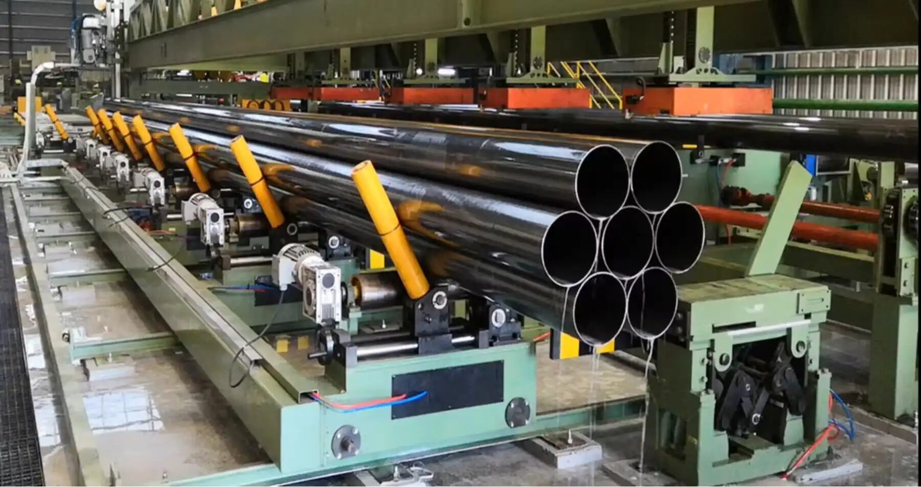
The journey towards a single-operator facility begins at the core of production: the steel pipe mill itself. Modern manufacturing has evolved to a point where a fully automated Electric Resistance Welded (ERW) tube mill can be procured as a turnkey solution, engineered from the ground up for continuous, “hands-off” operation. This foundational system takes raw steel coils and processes them into precisely cut pipes, forming the first and most crucial link in the automated value chain. The design philosophy of such a mill is to eliminate every traditional point of manual intervention, replacing it with reliable, integrated automation.
1.1. The Turnkey ERW Mill: A Foundational Overview
The basis for the autonomous production line is a state-of-the-art ERW tube mill, which can be sourced from global industrial engineering leaders who specialize in providing complete, integrated plant solutions.1 These turnkey systems are not merely collections of machines but are engineered as a single, cohesive unit designed for maximum automation, efficiency, and consistency.2 The process flow is a meticulously choreographed sequence of automated events, beginning with the loading of massive steel coils and concluding with the precise cutting of the finished pipe, all without requiring manual input during the production cycle.3 This automated foundation is essential, as any requirement for manual intervention at this primary stage would invalidate the single-operator concept for the entire facility.
1.2. Core Components and Automated Functions of the ERW Line
A detailed examination of the key stations within a modern, automated ERW line reveals how continuous, unmanned production is achieved. Each component is designed to perform its function and then seamlessly hand off the product to the next stage in the process.
- Uncoiler & Coil Loading: The process commences with a double-cone hydraulic uncoiler. This robust piece of equipment securely holds the steel coil, which can weigh many tons, and provides controlled tension as the strip is fed into the line. The critical automation feature here is the dual-cone or 180-degree rotary design, which allows a second coil to be loaded and prepared while the first is still running. When the active coil is depleted, the system can automatically begin feeding from the new coil, ensuring a non-stop supply of raw material into the mill.3
- Shear and Butt Welder: To create a truly continuous process from multiple discrete coils, an automated shear and butt welder is integrated directly after the uncoiler. This station automatically detects the end of the expiring steel strip and the beginning of the new one. It then precisely shears both ends to create clean edges and executes a perfect butt weld, joining the two coils into a single, uninterrupted strip. This function is one of the most significant automation enablers, as it completely eliminates the lengthy and labor-intensive process of manually stopping the line and re-threading a new coil.4
- Horizontal Strip Accumulator: The horizontal accumulator is arguably the most critical component for enabling continuous operation. It functions as a large-scale buffer, storing hundreds of meters of steel strip in a series of loops. Its purpose is to feed the forming section of the mill continuously while the shear and butt welder is momentarily paused to join the coils. Without this buffer, the entire line would have to stop every time a new coil is introduced. The accumulator provides the necessary time float for the upstream welding to occur without affecting the constant-speed downstream processes, thereby decoupling the two stages and allowing the line to function as a single, uninterrupted system.4
- Forming, Welding, and Sizing Units: Once the strip leaves the accumulator, it enters the forming section. Here, a meticulously designed series of rollers progressively shapes the flat steel strip into a round tube. This process is fully automated and requires no manual adjustment once programmed for a specific pipe dimension. The open seam of the newly formed tube then passes through a high-frequency induction welder. This technology, from specialized suppliers like Sanyi, generates intense heat to weld the seam, creating a strong, continuous bond.3 Immediately following the welder is an automated scarfing unit, which removes the exterior weld bead (burr) to create a smooth outer surface. The pipe then proceeds through a final set of sizing rollers, which ensure it meets the exact final diameter and roundness specifications.3 Depending on the specific application and material, the welding technology can be customized to use TIG, plasma, or laser welding for optimal results.3
- Automated Cutting (Cold Flying Saw): The final stage within the mill is the automated cutting system. A “flying saw,” typically a cold saw to ensure a clean, burr-free cut, is synchronized with the speed of the moving pipe. Based on pre-programmed length requirements, the saw travels with the pipe, makes a precise cut, and returns to its home position to await the next cut. This is accomplished without ever slowing or stopping the production line, a critical feature for maintaining high throughput. The newly cut pipes are then automatically transferred to an output roller table, ready for the next stage of the manufacturing process.4
1.3. Process Control and the “Digital Twin” Concept
The orchestration of these complex, high-speed mechanical processes is managed by a unified control system. At the base level, the entire ERW line is governed by a Programmable Logic Controller (PLC) system. The single operator interacts with this system through a Human-Machine Interface (HMI), allowing for the setting of parameters, monitoring of processes, and management of production runs from a central console.4 However, a truly advanced single-operator facility leverages the concept of the “Digital Twin,” a technology championed by firms like Siemens.5 A digital twin is a high-fidelity virtual model of the entire production line. This virtual representation is not static; it is fed with real-time data from the physical machines. This enables several powerful capabilities essential for designing and running a minimally staffed facility. Virtual commissioning allows the entire line and its control logic to be tested and debugged in a simulated environment before a single piece of steel is moved, drastically reducing physical setup time and risk. Furthermore, the digital twin can be used to simulate different production scenarios, optimize process parameters for efficiency, and predict the impact of changes without disrupting actual production. This level of advanced simulation and pre-planning can shorten the overall project duration by as much as 10% and allows for complex design and engineering work to be done by distributed teams remotely.6 The digital twin transforms the design process from one of sequential physical builds to parallel virtual optimization.
1.4. In-Line Quality Assurance – The First Checkpoint
To ensure product quality without constant human inspection, the first layer of automated quality control is integrated directly into the mill line. This is the initial sensory network of the plant, providing real-time feedback and enabling intelligent, self-correcting production.
- AI-Powered Visual Recognition: Immediately after forming and welding, the pipe can pass through an AI-driven inspection station. This system uses high-precision cameras and sophisticated deep learning algorithms to perform real-time surface defect detection. It can identify micron-level imperfections such as scratches, pores, or weld inconsistencies with an accuracy exceeding 99.5%.7 Case studies from industry leaders like Baosteel demonstrate that implementing such systems can lead to a 90% reduction in customer return complaints and a 60% decrease in labor costs associated with manual inspection.8
- Dynamic Parameter Optimization: The data from these in-line sensors feeds into an AI model that has been trained on vast amounts of production data. This AI can then make dynamic, real-time adjustments to critical process parameters like rolling speed, welding power, or cooling temperature to maintain optimal quality.7 This moves the facility beyond simple automation, where a machine follows a fixed program, to intelligent automation, where the system actively optimizes itself. This capability has been shown to improve product consistency by as much as 30% and significantly reduce process deviations.7
The existence of the horizontal accumulator is what makes the rest of the line’s automation possible. The forming mill must run at a constant, high speed for quality and efficiency. The process of joining two massive steel coils, however, is inherently intermittent; the strip must be stopped, cut, and welded. Without the accumulator’s ability to store a buffer of material, this start-stop action at the front of the line would force the entire continuous-flow process downstream to halt, destroying throughput and efficiency. The accumulator effectively decouples these two different operational cadences, allowing them to coexist within a single, seamless production stream. This dependency makes the accumulator’s performance a critical metric for the single operator to monitor.
This high level of automation fundamentally redefines the operator’s role. The integration of AI for dynamic optimization and the use of a digital twin for simulation mean the operator is no longer a machine tender who manually adjusts controls in response to alarms. They are a system supervisor. Their responsibility shifts to monitoring the performance of the AI, analyzing efficiency reports generated by the digital twin, and making high-level, strategic decisions about process improvements. The primary interface is not a set of physical controls, but a data-rich dashboard, demanding a skillset that is more analytical and data-centric than traditionally mechanical.
| Component | Function | Key Automation Feature | Contribution to Single-Operator Goal |
|---|---|---|---|
| Hydraulic Uncoiler | Holds and dispenses raw steel coil under tension. | Dual-cone or rotary design for pre-loading a second coil. | Eliminates downtime between coils, enabling continuous, uninterrupted material feed without operator intervention.4 |
| Shear & Butt Welder | Joins the end of one coil to the beginning of the next. | Automatic shearing and welding cycle triggered by sensors. | Creates a single, continuous steel strip from multiple coils, removing the need for manual line re-threading.4 |
| Horizontal Accumulator | Stores a buffer of steel strip. | Provides a continuous supply of material to the forming mill while the shear & welder is operating. | Decouples the intermittent coil-joining process from the continuous forming process, which is the lynchpin of non-stop production.4 |
| Forming & Sizing Unit | Progressively shapes the flat strip into a round pipe of a precise diameter. | Series of pre-set, automated rollers that require no adjustment during a production run. | Ensures consistent and accurate pipe dimensions without manual checks or mechanical adjustments.3 |
| High-Frequency Welder | Welds the seam of the formed tube. | Automated, high-speed induction welding process with precise power control. | Creates a strong, consistent weld seam at production speed, a task impossible to perform manually.3 |
| Scarfing Unit | Removes the external weld bead (burr). | Automated cutting tool that follows the weld seam. | Provides a smooth, finished pipe surface without manual grinding or finishing.3 |
| Cold Flying Saw | Cuts the continuous pipe into specified lengths. | Synchronizes with line speed to cut the pipe “on the fly” without stopping production. | Achieves high-throughput, precise-length cutting, eliminating a major manual handling and measurement step.4 |
| Output Conveyor | Transports finished pipes away from the mill. | Automated roller table that moves pipes to the next production stage. | Creates a seamless, automated handoff to the finishing line, removing the need for forklifts or cranes at this stage.4 |
2. Automated Finishing and Inspection: Perfecting the Product


Once the raw steel pipe has been formed, welded, and cut, it transitions to the finishing and inspection phase. In a traditional plant, this involves multiple, disconnected stages requiring significant manual handling, transportation, and setup. In the single-operator facility, these processes are integrated into a continuous, automated flow, directly downstream from the ERW mill. This section details how value-added processes like annealing, coating, and threading are automated and linked, culminating in a comprehensive, non-destructive quality gate that ensures every pipe meets specification before it is packaged.
2.1. Continuous In-Line Annealing
Immediately after being cut to length, pipes can be automatically conveyed into a continuous annealing furnace. Annealing is a critical heat treatment process that relieves the internal stresses induced during cold rolling and welding, thereby improving the pipe’s ductility and formability for downstream applications.9 For seamless integration, furnaces such as continuous roller hearth or induction types are ideal. These systems are designed to accept pipes directly from the mill’s output conveyor and process them in a continuous flow.10 The entire process is automated, with control systems managing the heating technology, which can be electric, gas, or diesel-fired.10 The furnace atmosphere is also precisely controlled, often using a nitrogen or hydrogen environment with advanced C-level control to achieve specific metallurgical properties and surface finishes, such as bright annealing, which prevents oxidation.11 The system automatically executes pre-programmed temperature profiles—including heating, soaking, and cooling phases—that are tailored to the specific grade of steel being processed, ensuring consistent and repeatable results without operator intervention.11
2.2. Robotic Coating and Curing Systems
Following annealing and cooling, the pipes proceed to a fully automated coating line. These systems are designed as self-contained cells that can be seamlessly integrated into the production flow, a critical feature for eliminating manual handling and protecting the operator from exposure to paints, powders, and volatile organic compounds (VOCs).12 The automated coating process involves several synchronized steps:
- Automated Loading and Surface Preparation: Robotic arms or automated conveyors take individual pipes from the annealing line’s output and place them onto specialized workpiece carriers. These carriers can then move the pipes through an integrated blasting station to prepare the surface for optimal coating adhesion.12
- Robotic Spraying: The pipe enters an enclosed spray booth where robotic arms apply the specified coating. This could be a Single or Dual Layer Fusion Bonded Epoxy (FBE), a three-layer polyethylene (3LPE) system, or other protective paints.13 The application is managed by a closed-loop digital gun control system that ensures precise and uniform coating thickness. These systems are highly flexible, capable of storing hundreds of programmable recipes for different pipe diameters, lengths, and coating specifications, allowing for rapid, automated changeovers.13
- Integrated Curing: After coating, the pipe is automatically conveyed through a series of integrated ovens for pre-heating and final curing. The curing method is tailored to the coating type and can involve hot air convection, induction heating, or UV lamps for specialized clear coats.12
- Specialized Internal Diameter (ID) Coating: For applications requiring internal protection, specialized ID Tube Spray Machines can be integrated into the line. These machines use a long spray lance that extends into the rotating tube to apply a uniform internal coating. Automating this process is a significant advancement in safety and quality, as manual ID coating is exceptionally difficult, hazardous, and prone to inconsistencies.14
2.3. Precision Automated Threading
The final finishing step is threading. Modern CNC pipe threading machines, designed for heavy-duty industrial environments, can be placed in-line after the coating and curing stage.15 These machines receive the coated pipe via an automated conveyor and perform the threading process without manual setup or handling. These advanced systems are capable of handling a wide range of pipe diameters, from as small as 1/2 inch up to 8 inches or more, and can be programmed to cut various thread types, including right-hand and left-hand threads, in a single, efficient pass.15 Key automation features include automatic die heads, which precisely cut the thread and then automatically open and release the pipe upon completion, and integrated through-the-head oiling systems that provide continuous lubrication and cooling during the cutting process.16 Because the entire operation is CNC-controlled, changeovers between different pipe sizes and thread specifications are purely programmatic, requiring only a command from the central control system rather than physical intervention.17
2.4. The Comprehensive Quality Gate: The Plant’s Nervous System
Before a pipe is cleared for packaging, it must pass through a final, all-encompassing quality gate. This is not a simple inspection station but a sophisticated, integrated cell that fuses multiple Nondestructive Testing (NDT) technologies. Its purpose is to provide 100% automated quality verification for every single pipe, serving as the plant’s final arbiter of quality and the critical safety net that makes a “lights-out” operation feasible. The power of this quality gate lies in its multi-technology approach, where each method provides a different piece of the quality puzzle18:
- Ultrasonic Phased Array (UT): This technology performs a volumetric inspection of the pipe. It sends ultrasonic waves through the material to detect internal defects like voids or laminations, verify weld penetration, and precisely measure the wall thickness across the entire pipe length.18
- Eddy Current Array: This method is used to inspect the pipe’s surface and near-surface for defects like cracks, seams, or laps that might not be visible to the naked eye.18
- X-Ray Inspection: An in-line X-ray system can be used to scan for internal contaminants and provide an additional layer of verification for the integrity of the weld seam.19
- Machine Vision & Laser Measurement: High-resolution cameras and laser scanners perform a 360-degree inspection of the pipe’s outer surface for coating imperfections, while also verifying the final diameter, ovality, and straightness. Specialized probes can even be used for internal chip detection.20
A critical feature of this automated quality gate is its data management capability. All inspection results from the various NDT systems are automatically logged and digitally tied to a unique identifier for each pipe or production batch. The system can automatically generate detailed defect reports and can be linked via industrial communication protocols like OPC-UA to both upstream and downstream equipment.21 Advanced software, such as Eagle’s TraceServer™, can consolidate this data from multiple machines into a single, centralized database, providing a complete, auditable record for traceability and due diligence purposes.19
The primary enabler of a true “lights-out” or single-operator manufacturing environment is the successful automation of this final, comprehensive quality gate. While each preceding stage of automation enhances efficiency, it also introduces the risk of propagating an undetected error across thousands of units. The most significant barrier to unattended production is the potential for catastrophic failure, such as producing an entire shift’s worth of out-of-spec parts.22 A human inspector can only sample a fraction of the output and is prone to error and fatigue. The integrated, multi-technology NDT cell provides a 100%, non-negotiable quality verdict on every single pipe. It combines ultrasonic, eddy current, X-ray, and machine vision systems to create a safety net that is far more reliable and comprehensive than any manual process. It is this automated assurance of quality that provides the necessary confidence for management to transition from a supervised production model to a fully autonomous one.
Furthermore, the vast amount of data generated by this integrated quality gate creates a powerful feedback loop, which is a cornerstone of Industry 4.0 principles. The data does not simply serve to accept or reject a finished pipe; it provides the diagnostic information to prevent future defects. For instance, the central MES can correlate a specific defect—such as an inconsistent coating thickness detected by the vision system20—with a specific event upstream, like a momentary temperature fluctuation in the pre-heating oven logged by the SCADA system. The single operator can then analyze this correlation and instruct the plant’s AI control system7 to adjust its heating parameters proactively, thereby preventing the defect from recurring in subsequent batches. This transforms the function of quality control from a reactive, cost-incurring activity (finding and scrapping mistakes) into a proactive, value-creating engine (analyzing data to prevent mistakes from ever happening).
3. From Pipe to Pallet: Automated Counting, Bundling, and Strapping


After the steel pipes have been manufactured, finished, and have passed the final quality inspection, they must be prepared for storage and transport. This stage involves counting the individual pipes, arranging them into stable bundles, and securing them for handling. In a conventional facility, this is a highly manual, physically demanding, and repetitive process. In the single-operator plant, this entire workflow is handed over to a dedicated, fully automated bundling and strapping line that seamlessly converts a stream of individual pipes into secure, transport-ready units.
3.1. The Automated Bundling and Strapping Line
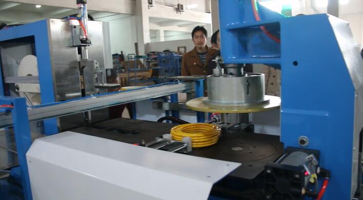
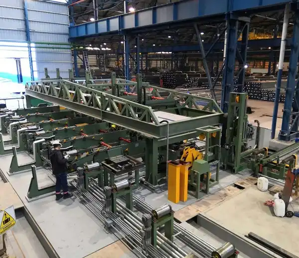
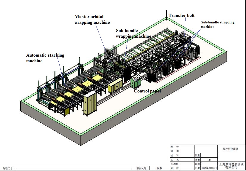
The automated packaging cell is a sophisticated piece of machinery that executes a sequence of tasks to prepare the pipes for the warehouse. This process, detailed by equipment providers, follows a logical, hands-free progression.23
- Pipe Infeed and Counting: Finished pipes are conveyed from the final inspection gate directly to a storage or accumulation table on the bundling line. From here, a lifting and separating mechanism feeds the pipes one by one onto a transfer conveyor. As they move, they pass through an automated counting system, which can use sensors or vision systems to maintain an accurate tally.23
- Bundle Formation: The system is programmed with the desired number of pipes per bundle. Once the counter reaches this pre-set quantity, a stop lever or gate is actuated, releasing the group of pipes into a collection area or “material catcher.” This catcher is often shaped to form the pipes into a specific bundle geometry, such as a hexagon or square, which provides greater stability for stacking and transport compared to a simple round bundle.23
- Alignment and Conveying: The newly formed, but still loose, bundle is then transferred by a cradle roller or a similar conveying system toward the strapping station. During this transfer, an alignment mechanism, which may consist of adjustable guides or clamps, ensures the pipes are neatly arranged and the bundle is compact and correctly shaped before it is secured.24
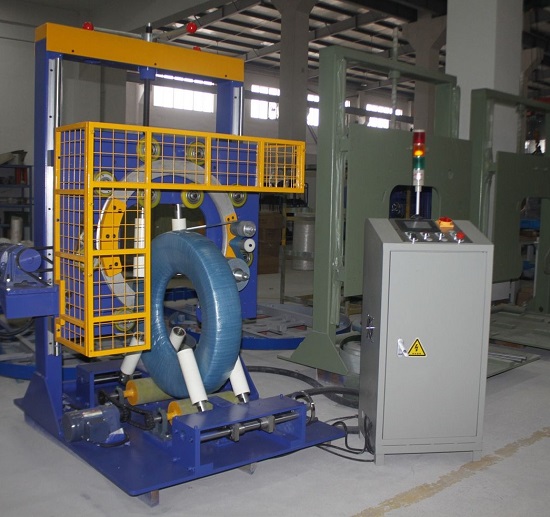
- Automated Strapping and Wrapping: At the strapping station, the core packaging process takes place. The machine automatically applies high-tensile steel or PET/PP strapping around the bundle at pre-determined locations along its length. The strapping head automatically tensions the strap to the correct specification, seals it (often using a heat-weld for plastic straps), and then cuts it cleanly. The entire cycle is repeated for each strapping position.25 As an alternative or additional step, some systems can be configured to wrap the bundles in adhesive tape or stretch film for added protection and stability.23
- Stacking and Unloading: Once the bundle is fully strapped, it is considered a finished unit. An ejector mechanism pushes the completed bundle from the strapping station onto an adjacent stacking area or output conveyor. Here, the machine can be programmed to accumulate and stack the bundles into layers, preparing a full pallet’s worth of product. When the stack is complete, the system signals its readiness for pickup, at which point it becomes the responsibility of the autonomous logistics systems detailed in the following sections.23
3.2. System Flexibility and Control
The entire bundling and packaging line is governed by its own PLC, which is in turn integrated into the plant-wide MES. This allows the single operator to manage and modify all packaging parameters from the central control room via an HMI.26 This programmatic control provides immense flexibility. The operator can easily change recipes to accommodate different pipe diameters and lengths, adjust the number of pipes per bundle, change the bundle shape, specify the number and location of straps, and select the type of packaging material (e.g., steel strap, plastic strap, or tape). This ability to rapidly and automatically change over between different product runs is essential for an efficient and agile manufacturing operation. The technology is versatile enough to be designed for a wide array of products, including standard steel pipes, stainless steel tubes, and even PVC pipes, demonstrating its broad applicability.23
The successful automation of the entire packaging process hinges on the direct, closed-loop integration of the counting system with the bundle formation mechanism. In a hypothetical semi-automated scenario, an operator would have to manually count the pipes or visually confirm a batch before triggering the bundling cycle. This would introduce a significant bottleneck, require constant human attention, and fundamentally break the “single-operator” model. The process described by equipment manufacturers, where the sensor-based counting system automatically actuates the release mechanism once a pre-set number is reached, is the critical link that enables the entire subsequent sequence of forming, strapping, and stacking to proceed autonomously for each and every bundle without any human intervention.23
The output of this automated bundling station creates a standardized “unit of handling” that dictates the design and operational parameters for all subsequent logistics systems within the facility. The decisions made by the single operator on the bundling machine’s HMI—defining the bundle’s final dimensions, shape (e.g., hexagonal), and weight—have a direct and cascading impact on the physical and software requirements of the downstream infrastructure. The payload capacity and chassis design of the heavy-duty AGVs, the size and weight limits of the AS/RS storage cassettes, and the design of the robotic truck loader’s end-of-arm tooling must all be engineered specifically to handle the exact form factor produced by this station.27 This deep, physical interdependency underscores the level of holistic, integrated planning required to design a successful single-operator facility, where a change in one module has direct consequences for all others.
4. The “Lights-Out” Warehouse: Automated Intralogistics

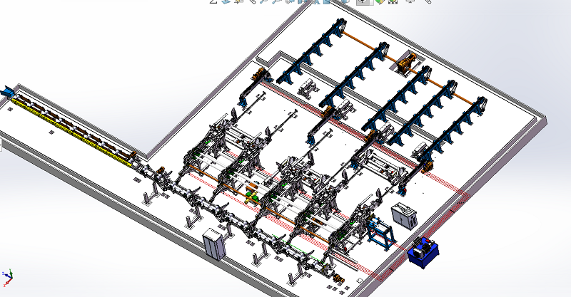
With finished, bundled, and stacked pipes ready for storage, the next phase of automation addresses the challenge of intralogistics. The “lights-out” warehouse is a concept where inventory is managed, stored, and retrieved with minimal or no human presence on the floor. This is achieved through the implementation of high-density Automated Storage and Retrieval Systems (AS/RS), orchestrated by a sophisticated Warehouse Management System (WMS). This approach not only maximizes storage capacity but also provides perfect inventory accuracy and control, essential components of a single-operator ecosystem.
4.1. Automated Storage & Retrieval Systems (AS/RS) for Long Goods
Traditional warehouses for long and heavy goods like steel pipes are space-intensive, relying on cantilever racking and significant aisle space for forklifts or overhead cranes. An AS/RS completely transforms this model by utilizing vertical space, dramatically increasing storage density and reducing the required footprint.28 These systems are specifically engineered to handle the unique challenges of long, heavy, and bulky materials. Several types of AS/RS are particularly well-suited for a steel pipe facility:
- Honeycomb Warehouse: This system consists of a rack structure with a multitude of cassette-based storage locations, resembling a honeycomb. A high-speed, overhead Storage and Retrieval Machine (S/RM) travels along an aisle, accessing any cassette directly. This design is ideal for operations with a high number of different product SKUs, as it provides fast, random access to any stored bundle. These systems are highly scalable for large quantities of material.28
- Bridge Storage System: Similar to a honeycomb system, the bridge storage design uses an overhead S/RM, but it is optimized for extreme storage density with very narrow aisles. This is an excellent solution when maximizing the use of a limited floor area is the primary objective.28
- Tower Storage System: For facilities with more limited storage needs or where vertical space is the main asset, a tower storage system offers a compact solution. These systems, such as the TRUMPF TruStore or the Remmert BASIC Tower, are essentially vertical lift modules (VLMs). Bundles are stored on trays or cassettes within a tall, enclosed tower, and an internal elevator mechanism retrieves the required tray and presents it at an access point. While highly space-efficient, their throughput can be lower than honeycomb systems for high-volume operations.28
In each of these systems, the process is fully automated. An AGV (as detailed in Section 5) delivers a finished pipe bundle from the packaging line to a designated loading station at the AS/RS. The system automatically takes the bundle, places it into a cassette, and the S/RM stores the cassette in an optimized location within the racking. The reverse process occurs for retrieval: upon receiving an order, the S/RM retrieves the correct cassette and delivers it to an unloading station for an AGV to pick up and transport to the shipping bay.
4.2. The Warehouse Management System (WMS) and Control
The WMS is the intelligent software layer that acts as the brain of the automated warehouse. It provides the single operator with complete, real-time visibility and control over every item in inventory.28 The WMS is not a standalone program; it is deeply integrated with both the physical AS/RS hardware and the plant’s overarching Manufacturing Execution System (MES).29 The key functions of the WMS include:
- Inventory Tracking: From the moment a bundle is inducted into the AS/RS, the WMS tracks its exact location. This eliminates the possibility of lost or misplaced inventory.
- Order Management: The WMS receives storage and retrieval orders directly from the MES. When a new bundle is produced, the MES instructs the WMS to store it. When a customer order needs to be shipped, the MES tells the WMS which bundles to retrieve.
- Storage Optimization: The WMS uses sophisticated algorithms to decide where to store each cassette. It may place high-turnover items closer to the access points to minimize S/RM travel time, or it can group similar items together, constantly optimizing the storage layout for maximum efficiency.
- Data Integration: The WMS provides a continuous flow of real-time inventory data back to the MES and the company’s Enterprise Resource Planning (ERP) system, enabling accurate, up-to-the-minute business intelligence.
4.3. Case Study: Matter srl Automated Warehouses
A practical example of these principles can be seen in the solutions offered by Matter srl, an Italian company specializing in custom-made, high-density storage systems for the steel industry.30 They design and implement automatic warehouses specifically for tubes and bundles up to 12 meters in length.30 The stated benefits of their systems align perfectly with the goals of a single-operator facility: faster loading and unloading operations, significantly reduced order processing times, lower operating costs, and a dramatic increase in operational safety and efficiency. Their systems are built around the core principles of precise material selection and complete digital traceability, which are non-negotiable requirements for an automated warehouse managed by a single person.31
The physical architecture of the AS/RS and the software logic of the WMS are not independent variables; they are deeply and inextricably linked. The decision to implement a honeycomb system versus a tower system, for example, is not merely a hardware choice. It fundamentally dictates the software algorithms that the WMS must employ for put-away and retrieval strategies, which in turn governs the overall throughput and efficiency of the warehouse. A honeycomb system allows for random, direct access to a large number of SKUs, making it highly efficient for high-mix, variable-demand environments.28 The corresponding WMS logic would prioritize optimizing S/RM travel paths for random retrievals. In contrast, a tower system is a “last-in, first-out” or sequenced system within its vertical stack.32 The WMS logic for a tower must be optimized for sequencing, perhaps storing the most frequently ordered items near the top or bottom access point. The single operator, interacting with the system through the MES/WMS interface, must understand this symbiotic relationship between the physical layout and the control logic to effectively manage warehouse performance.
The most profound implication of implementing a “lights-out” warehouse is the fundamental transformation of inventory itself. In a traditional warehouse, inventory is a physical asset that requires periodic, labor-intensive manual counts and is often a source of financial liability due to carrying costs and potential inaccuracies. In a fully automated warehouse managed by an integrated WMS, inventory becomes a real-time data asset.28 The exact quantity and location of every single bundle are known with perfect accuracy, 24/7. This live data stream can be fed directly from the WMS into the company’s ERP system. This has transformative effects on the entire business: the sales department has an exact, to-the-second view of what is available to promise to customers; the finance department has a real-time, accurate valuation of inventory on hand; and the procurement department can automate raw material orders based on precise, real-time consumption rates and finished goods levels. The warehouse is no longer just a building for storage; it becomes a live, dynamic node in the company’s integrated digital ecosystem, a core tenet of the Industry 4.0 revolution.33
5. Autonomous Logistics: The Final Mile to the Truck


The final stage in the automated physical workflow involves moving the finished, bundled pipes from their storage location in the warehouse to the shipping dock and loading them onto the designated delivery vehicle. This “final mile” of internal logistics, traditionally handled by forklifts and manual labor, is fully automated through the deployment of a fleet of heavy-duty Automated Guided Vehicles (AGVs) and specialized robotic loading systems. This ensures the hands-off chain of custody continues right up to the point of departure.
5.1. Heavy-Duty Automated Guided Vehicles (AGVs) for Yard Management
AGVs are the backbone of the facility’s transport system, responsible for all material movement outside of the fixed conveyors of the production and packaging lines. For a steel pipe plant, these are not the small, light-load carriers seen in e-commerce warehouses; they are robust, custom-engineered vehicles designed to handle immense weights and bulky loads safely and autonomously.34
- Payload and Design: These AGVs are built for heavy industry. Companies like Morello offer customized AGVs with capacities ranging from 2 tons to over 1,000 tons, with specific models designed for the transport of steel pipes and coils.27 Remmert’s platform AGV is another prime example, specifically designed to transport long goods up to 8 meters in length with a payload of 3 tons. A key feature of such advanced AGVs is an omnidirectional drive system, which allows the vehicle to move not only forward and backward but also sideways and rotationally. This enables navigation through narrow and confined spaces that would be impossible for a traditional forklift, maximizing floor space utilization.35
- Navigation Technologies: The method by which an AGV navigates is a critical design choice that determines its flexibility and operational domain.
- Laser Navigation (LIDAR): This is the most advanced and flexible method. The AGV uses rotating laser scanners to detect either specially placed reflectors or existing structural features of the plant (like walls and columns), a technique known as natural feature or contour navigation. It uses this data to triangulate its position in real-time. Routes can be changed easily and quickly via software, making it ideal for dynamic environments.35
- Magnetic/Wired Guidance: In this method, the AGV follows a physical path, such as magnetic tape applied to the floor or a wire embedded in the concrete. While reliable and cost-effective for simple, fixed routes, this method is inflexible and requires significant work to alter paths.34
- dGPS Guidance: For travel between buildings or across outdoor yards, differential GPS (dGPS) provides precise positioning where laser or magnetic guidance is not feasible.27
- Optical Guidance: This method involves the AGV following a painted line on the floor, offering easier installation than wired guidance but less flexibility than laser navigation.36
- Safety and Control: Safety is paramount in a system where multi-ton autonomous vehicles operate. These AGVs are equipped with a comprehensive suite of safety devices, including 360-degree laser scanners (which serve for both navigation and safety), physical bumpers, and cameras. These systems detect any obstacles or personnel in the vehicle’s path and will automatically slow down or stop to prevent collisions.35 The entire fleet of AGVs is orchestrated by a central fleet management controller, which is integrated with the WMS and MES. This controller receives transport orders (e.g., “move bundle X from AS/RS output C to loading bay 2”), optimizes routes, manages traffic, and dispatches the appropriate AGV for the task.34