How Do You Set Up Remote Monitoring Systems for Mold Upenders?
Struggling with unexpected downtime on your mold upenders? Unsure if your equipment is operating at peak efficiency? Implementing remote monitoring can provide the crucial data needed for optimization, but the setup process can seem daunting. Gain real-time insights and prevent costly failures before they happen.

Setting up a remote monitoring system for mold upenders involves defining monitoring goals (e.g., cycle time, load, tilt angle), selecting appropriate sensors (position, load cells, hydraulic pressure), choosing data acquisition hardware (RTU/PLC, Edge Gateway), establishing a secure communication network (wired/wireless), configuring a monitoring platform (SCADA/RMM) for data visualization and alerts, and implementing robust data security measures. This ensures real-time operational visibility and proactive maintenance capabilities.
Understanding the intricacies of each step is vital for a successful implementation. This guide delves into the specifics, from initial planning and component selection to deployment strategies and security protocols, ensuring your mold upender monitoring system delivers maximum value and reliability. Read on to discover the detailed process.
Planning Your Monitoring Architecture for Mold Upenders
Embarking on remote monitoring for your mold upenders requires a clear blueprint. Without proper planning, you risk deploying a system that’s either inadequate or overly complex, failing to deliver the desired insights. A well-thought-out architecture ensures you capture the right data, transmit it reliably, and receive actionable alerts, forming the foundation for optimized performance and predictive maintenance of your critical mold handling equipment.
To effectively plan your mold upender monitoring architecture, first, meticulously identify all critical parameters you need to monitor, such as tilt angle, cycle time, load weight, hydraulic pressure, motor current, and vibration levels. Calculate the number of discrete (on/off status) and analog (variable readings) points required. Second, determine the most suitable data backhaul method based on site infrastructure (IP network, cellular, fiber). Ensure compatibility between your Remote Terminal Unit (RTU) or gateway protocols (e.g., Modbus, SNMP) and your central system. Third, define your preferred notification methods (GUI, email, SMS, voice call) and establish filtering rules to prioritize critical alerts, ensuring timely responses without unnecessary noise.
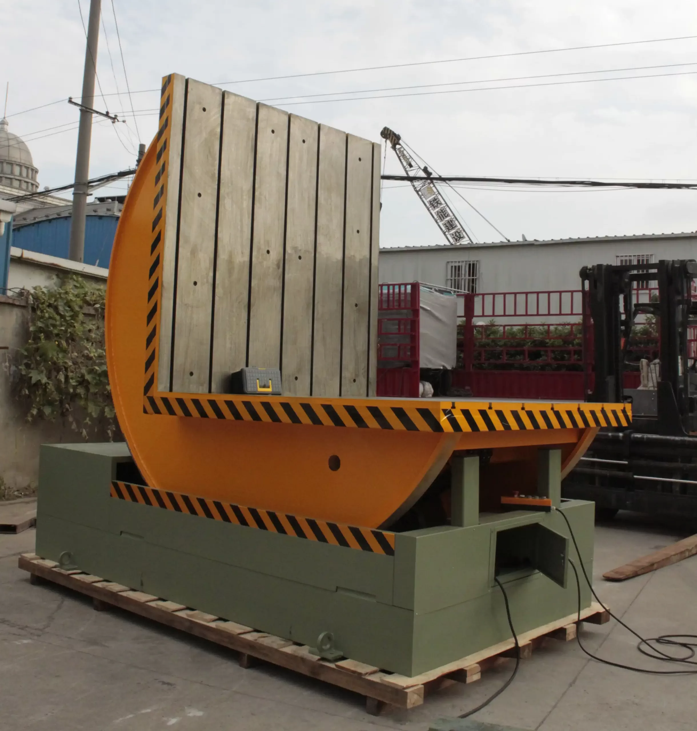
Key Considerations for System Design
Successfully designing a remote monitoring system for mold upenders hinges on a detailed understanding of your specific operational needs and environmental constraints. This involves more than just picking hardware; it requires a strategic approach to ensure the collected data is relevant, accurate, and securely transmitted for effective analysis and action.
H3: Defining Monitoring Scope (What to Monitor)
The initial and most critical step is deciding precisely what aspects of the mold upender’s operation need oversight. Start by listing all potential monitoring points. For mold upenders, key parameters often include:
- Operational Status: Is the upender running, idle, or faulted? (Discrete Point)
- Tilt Angle: Real-time angle of the platform. (Analog Input)
- Load Weight: Measuring the weight of the mold being handled. (Analog Input – Requires Load Cells)
- Hydraulic System: Pressure and fluid levels. (Analog Inputs)
- Motor Performance: Current draw, temperature, vibration. (Analog Inputs)
- Cycle Time: Duration of the upending process. (Calculated from other data or discrete triggers)
- Safety Interlocks: Status of gates, light curtains, emergency stops. (Discrete Points)
- Environmental Conditions: Temperature near critical components. (Analog Input)
Quantify these needs. Calculate the total number of discrete points (on/off, open/closed) and analog inputs (measuring ranges like pressure, temperature, angle). Don’t forget potential future expansion. Choose an RTU or gateway with spare capacity to accommodate growth without requiring immediate hardware replacement. Consider internal points as well – monitoring the health of the RTU/gateway itself is crucial.
| Monitoring Point Type | Description | Example on Mold Upender | Data Type | Purpose |
|---|---|---|---|---|
| Discrete Points | Binary status (On/Off, Open/Closed, Fault/OK) | Motor Running Status, E-Stop Active | Boolean | Basic operational state, safety checks |
| Analog Inputs | Variable measurements within a defined range | Tilt Angle (0-90°), Hydraulic Pressure | Float/Int | Performance tracking, condition monitoring |
| Calculated Points | Derived from other measured data points | Cycle Time, Load Imbalance | Varies | Efficiency analysis, advanced diagnostics |
| Internal Points | Monitors the status of the monitoring device | RTU Power Status, Network Connection | Varies | Ensures monitoring system reliability |
H3: Selecting Data Transmission Methods (Backhauling)
Once data is collected by sensors and processed by the local RTU or gateway, it must be transmitted (“backhauled”) to a central monitoring station or cloud platform. The choice of method depends heavily on the infrastructure available at the mold upender’s location:
- Wired Ethernet (IP): Offers high speed and reliability if network infrastructure is readily available. Common in modern manufacturing facilities.
- Fiber Optic: Provides immunity to electromagnetic interference (common in industrial settings) and high bandwidth, but requires specific infrastructure.
- Cellular (4G/5G): Excellent for locations without existing network drops or for mobile upenders. Requires good signal strength and a data plan.
- Wi-Fi: Suitable for shorter distances within a facility with existing Wi-Fi coverage, but potential interference needs consideration.
- Satellite: Viable for extremely remote locations with no other connectivity, but typically higher latency and cost.
Equally important is protocol compatibility. The RTU/gateway must communicate using a protocol understood by the central master station or platform (e.g., SCADA, RMM). Common industrial protocols include Modbus (RTU/TCP), SNMP, DNP3, MQTT, and OPC-UA. Selecting hardware that supports multiple protocols and transport methods provides flexibility and future-proofing.
H3: Establishing Notification Protocols
Raw data is useless without interpretation and timely alerts. The central monitoring system must translate incoming data into actionable information. Define how personnel should be notified of different event severities:
- Graphical User Interface (GUI): Dashboards showing real-time status, often with map views or process diagrams. Ideal for operators in a control room. Color-coded indicators (green/yellow/red) or blinking icons highlight issues.
- List Displays: Alarm logs showing events chronologically, similar to an email inbox.
- Email Notifications: Suitable for routine alerts or reports sent to specific personnel or distribution lists.
- SMS Alerts: Effective for critical alarms requiring immediate attention, especially for personnel outside the control room or after hours.
- Voice Calls (Automated): Can be used for escalating highly critical alarms to ensure acknowledgment.
Crucially, implement intelligent alarm filtering. Not every deviation warrants a 3 AM wake-up call. Configure the system to differentiate between minor warnings (e.g., approaching maintenance interval) and critical failures (e.g., overload detected, safety interlock failure). Define escalation paths based on severity and time.
Implementing the Remote Monitoring System: A Step-by-Step Guide
Transitioning from planning to execution requires a structured implementation process. Deploying remote monitoring for mold upenders involves integrating hardware and software, configuring parameters, testing thoroughly, and training staff. A methodical approach minimizes disruption, ensures data accuracy, and accelerates the realization of benefits like improved uptime and predictive maintenance for your valuable mold upender.
Successful implementation typically follows these key steps: Define clear success criteria (e.g., 15% reduction in unexpected downtime, real-time load monitoring achieved). Determine the deployment strategy (phased rollout, agent installation method). Evaluate and migrate any existing monitoring scripts. Conduct a gap analysis for necessary data points. Perform rigorous lab and pilot testing. Develop Key Performance Indicators (KPIs). Train support teams. Configure smart alerts and automated responses where feasible. Establish regular monitoring analytics and reporting.
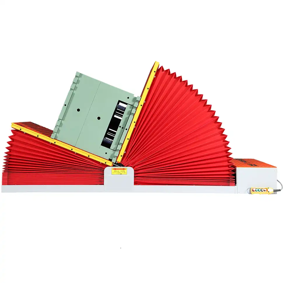
Deployment and Configuration Process
Bringing your remote monitoring system online involves careful coordination and technical execution. Adhering to a structured process ensures that the system integrates smoothly with your existing operations and starts delivering value quickly. The timeline can vary (often 3-6 months from selection to value realization), depending on complexity and resources.
-
Define Clear Implementation Success Criteria (2–3 weeks): What constitutes a successful deployment? Go beyond just “system is online.” Define measurable goals tied to business needs. Examples for a mold upender: Achieve real-time visibility of tilt angle and load within 5% accuracy; Reduce unscheduled downtime due to hydraulic issues by 20% within 6 months; Implement alerts for overload conditions that trigger within 10 seconds. Gain cross-functional alignment on these benchmarks.
-
Determine Your Deployment Strategy (1–5 days): How will the monitoring hardware/software agent be installed? If remote updates are possible via an existing network, deployment can be swift. If physical access is required (installing sensors, gateways), factor in scheduling, potential downtime, and technician availability. Consider a phased rollout, starting with one or two non-critical upenders.
-
Evaluate Existing Tools/Scripts (1–2 weeks, parallel): If you have existing monitoring scripts or basic systems, review them. Can they be integrated? Does the new system replace them? Migrate necessary custom scripts (e.g., specific fault logic) to the new platform. Avoid redundant functionalities to reduce complexity and cost.
-
Gap Analysis in Monitoring Data (1–3 weeks): Revisit the data points identified during planning. Does the chosen hardware provide all necessary data? For instance, can you differentiate between the motor running and the upender actually moving? Is vibration analysis needed? This phase might reveal needs for additional sensors or custom software development (e.g., interfacing with a proprietary controller) to expose critical status information (like specific error codes) to the monitoring system.
-
Lab and Pilot Testing (2–4 weeks): Before full deployment, test rigorously. Set up the system in a controlled lab environment or on a single pilot mold upender. Verify sensor accuracy, data transmission, platform connectivity, and basic alert functions. Work with the vendor’s support team. Address firewall rules and any initial performance impacts. This iterative phase is crucial for identifying and resolving issues early.
-
Data Analysis and KPI Development (2–3 weeks, parallel with testing): As data flows from the pilot system, start developing specific Key Performance Indicators (KPIs). Examples for mold upenders: Average Cycle Time, Peak Load vs. Rated Capacity, Hydraulic Pressure Variance, Number of Emergency Stops, Uptime Percentage. Define how these KPIs are calculated within the monitoring platform. Aim for 3-5 core KPIs initially.
-
Train Your Support Team (4–8 weeks, parallel): Training is critical. Identify who needs to use the system (Operators, Maintenance L1/L2/L3, Engineers). Use a “train the trainer” approach or vendor-provided training. Focus on practical skills: navigating the dashboard, interpreting data, acknowledging alerts, using remote troubleshooting tools (if applicable), generating reports. Allow time for Q&A and feedback.
-
Smart Alerting and Automated Resolution (4–8 weeks, parallel/ongoing): Configure alerts based on the KPIs and critical thresholds defined earlier. Start with essential alerts (e.g., E-stop activated, overload, communication loss). Gradually implement more nuanced alerts (e.g., high vibration trend, slow cycle time). Explore automation possibilities: Can the system automatically log a maintenance ticket for certain alerts? Note: Automated control actions on heavy machinery like mold upenders require extreme caution and safety validation.
-
Monitoring Analytics and Reporting (1–2 days, recurring): Establish reporting routines (daily, weekly, monthly). Use the platform’s analytics tools to track KPIs, identify trends, analyze downtime causes, and measure the impact of the monitoring system against the initial success criteria. Custom dashboards might be needed to visualize data specific to your operation. This is an ongoing process of refinement.
Core Components of a Mold Upender Remote Monitoring System
Facing inconsistent performance from your mold upenders? Implementing remote monitoring requires specific hardware and software working in concert. Without the right components, you’ll lack the data fidelity needed for accurate diagnostics and predictive maintenance, leaving you vulnerable to unexpected failures and inefficiencies in your mold handling process.
A typical remote monitoring system for a mold upender comprises: 1. Sensors specifically chosen for the application (e.g., inclinometers, load cells, pressure transducers, vibration sensors). 2. Data Acquisition Hardware (DAQ), such as a Remote Terminal Unit (RTU), PLC, or an IoT Edge Gateway, to collect and preprocess sensor data. 3. A reliable Communication Network (wired Ethernet, cellular, Wi-Fi) to transmit data. 4. A central Monitoring Platform (SCADA, RMM, or cloud-based IoT platform) for data storage, visualization, analysis, and alerting.
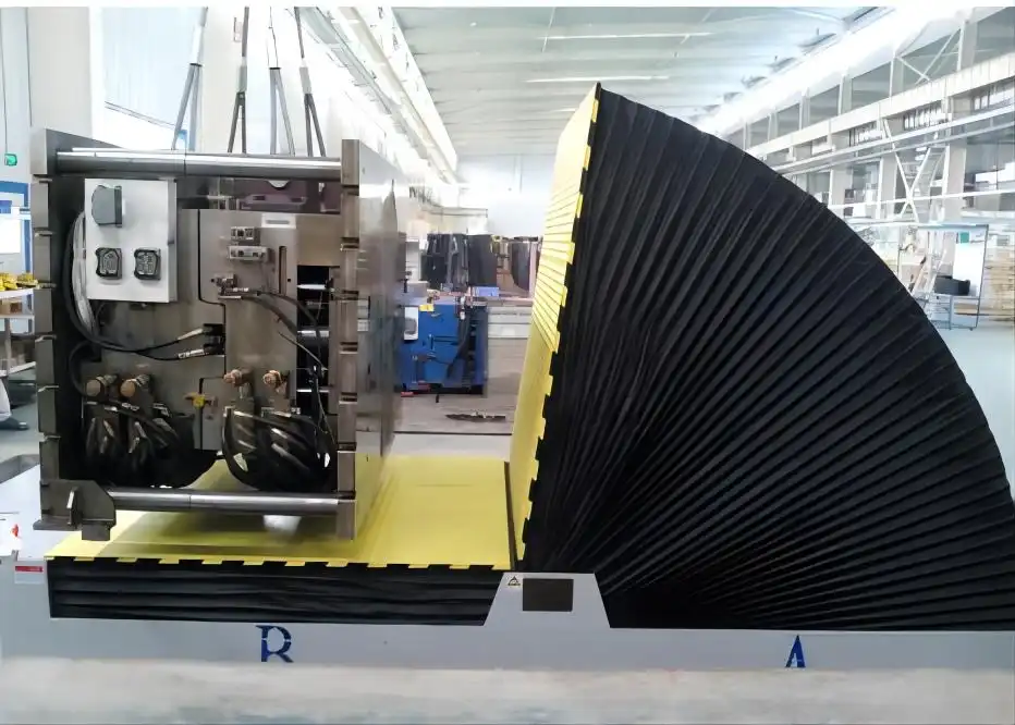
Hardware and Software Essentials
Selecting the appropriate components is fundamental to building an effective remote monitoring system. Each element plays a distinct role in the chain, from capturing raw physical data at the machine to presenting actionable insights to operators and maintenance teams.
H3: Sensors and Data Acquisition Hardware
This is where the physical world meets the digital. The choice of sensors dictates the quality and type of data you can collect directly from the mold upender.
- Sensors:
- Inclinometers/Tilt Sensors: Measure the precise angle of the upender platform. Crucial for cycle tracking and ensuring correct positioning.
- Load Cells: Integrated into the platform structure or lifting mechanism to measure the weight of the mold accurately. Essential for overload prevention and operational logging.
- Hydraulic Pressure Sensors/Transducers: Monitor pressure in the hydraulic lines, vital for detecting leaks, pump issues, or blockages.
- Position Sensors (Limit Switches, Proximity Sensors, Encoders): Detect the position of moving parts (e.g., end-of-travel, clamp status).
- Vibration Sensors (Accelerometers): Can detect bearing wear, imbalance, or other mechanical issues developing in motors or gearboxes.
- Temperature Sensors: Monitor motor, hydraulic fluid, or bearing temperatures to prevent overheating.
- Current Sensors: Measure motor current draw, indicating load and potential electrical issues.
- Data Acquisition (DAQ) Hardware: This hardware gathers signals from the sensors, digitizes them, and prepares them for transmission.
- Remote Terminal Unit (RTU): Robust devices designed for industrial environments, often with built-in communication capabilities and protocol support (Modbus, DNP3).
- Programmable Logic Controller (PLC): While primarily for control, modern PLCs often have sufficient capabilities to acquire data and communicate with higher-level systems. Integration might be simpler if a PLC already controls the upender.
- IoT Edge Gateway: Devices like the mentioned IG502 specialize in connecting industrial equipment to networks (especially IoT platforms). They often perform local data filtering, preprocessing, and aggregation before transmitting, reducing network load and providing faster local responses if needed. They typically support various industrial protocols and network interfaces (Ethernet, Wi-Fi, 4G/5G).