Can 3D Printing Improve Mold Upender Performance Through Custom Parts?
Struggling with standard mold upender components that limit efficiency or can’t handle unique mold geometries? These limitations often lead to slower cycle times, increased wear, and potential safety risks. Imagine optimizing your upender with parts perfectly tailored to your needs, boosting performance and durability.
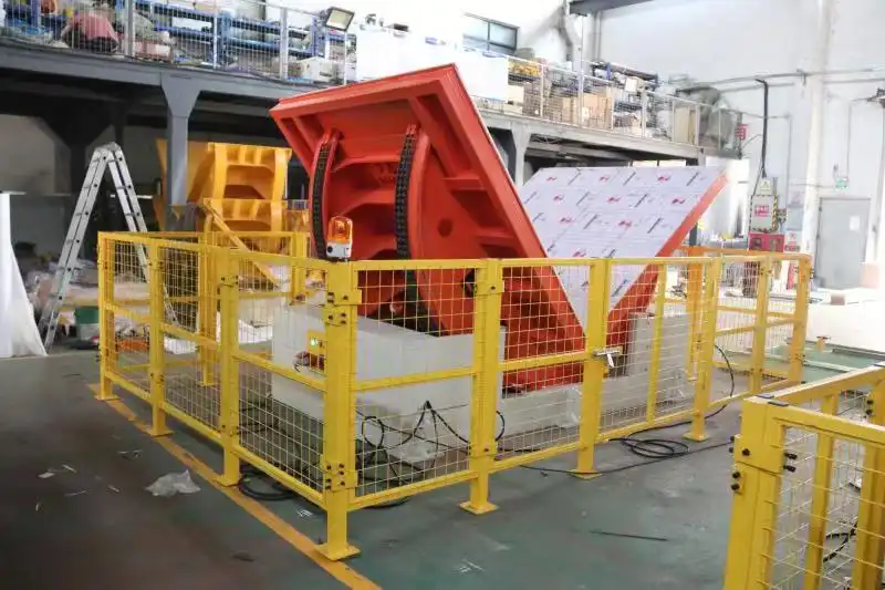
Yes, 3D printing, or additive manufacturing (AM), can significantly improve mold upender performance. It enables the rapid creation of custom-designed components like grippers, supports, or wear pads tailored to specific molds or operational demands. This customization leads to better fit, function, enhanced durability, and optimized weight, boosting overall efficiency and reducing downtime.
This shift from standard, off-the-shelf parts to bespoke, 3D-printed solutions is unlocking new levels of performance in heavy equipment operation. Read on to discover how additive manufacturing is specifically revolutionizing mold upender functionality through tailored components.
The Role of Customization in Upender Efficiency
Standard mold upenders are built for general tasks, but manufacturing often involves unique challenges – specific mold sizes, weights, or handling requirements. Relying solely on standard parts can bottleneck efficiency. How can tailoring components specifically for your needs, using 3D printing, break through these limitations and elevate upender performance?
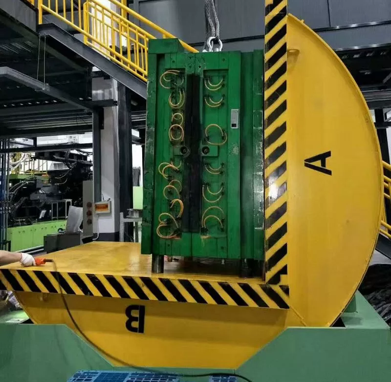
Customization through 3D printing allows for the design and production of mold upender parts perfectly matched to specific operational requirements or mold geometries. This includes creating unique fixtures, guides, protective padding, or even lightweight structural elements impossible with traditional methods. These tailored components can reduce mold slippage, improve load positioning accuracy, minimize cycle times by optimizing movement paths, decrease wear on both the mold and the upender, and enhance operator safety, directly contributing to a more efficient and reliable operation.
Technical Deep Dive: From Design to Optimized Part
Achieving enhanced upender performance through 3D printing involves a systematic approach, moving from identifying needs to implementing tested, custom components. This process leverages the unique capabilities of additive manufacturing at each stage.
Identifying Optimization Opportunities
The first step is a thorough analysis of the current mold upender’s operation. This involves identifying bottlenecks, points of excessive wear, areas where standard components underperform, or specific challenges posed by particular molds. Are cycle times slow due to awkward positioning? Is a specific mold type prone to damage during tilting? Are standard wear pads failing prematurely? Data collection through observation, operator feedback, and maintenance logs is crucial here. Understanding these pain points defines the requirements for custom parts.
Designing Custom Components with AM in Mind
Once opportunities are identified, the design phase begins, utilizing Computer-Aided Design (CAD) software. This is where the power of Design for Additive Manufacturing (DfAM) comes into play. Engineers aren’t constrained by traditional manufacturing limitations. They can:
- Create Complex Geometries: Design parts with internal channels (e.g., for cooling or lubrication if needed, though less common for upenders), intricate surface textures for better grip, or organic shapes that conform perfectly to specific mold contours.
- Leverage Topology Optimization & Generative Design: Use software algorithms to create lightweight yet strong structures by removing material from non-critical areas while reinforcing load paths. This is ideal for reducing the inertia of moving parts or replacing heavy metal components.
- Consolidate Parts: Redesign assemblies previously made of multiple components into a single, complex 3D-printed part. This simplifies assembly, reduces potential failure points, and can improve structural integrity.
Material Selection for Durability and Function
Choosing the right material is critical for the success of custom upender parts. AM offers a growing range of options:
- Engineering Polymers: Materials like Nylon, ABS, PETG, or Polycarbonate offer good strength, impact resistance, and wear properties for applications like custom guides, bumpers, or non-load-bearing fixtures.
- Composites: Fiber-reinforced materials (e.g., Carbon Fiber Nylon, Fiberglass Nylon) provide significantly higher strength, stiffness, and durability compared to standard polymers, making them suitable for more demanding applications like custom grippers or support structures, potentially replacing metal parts for weight savings.
- Metals: Technologies like Direct Metal Laser Sintering (DMLS) or Selective Laser Melting (SLM) can print parts in stainless steel, tool steel, or aluminum alloys. This is ideal for critical structural components, high-wear surfaces, or parts requiring maximum strength and rigidity.
The choice depends on the specific application’s requirements for strength, weight, wear resistance, temperature tolerance, and cost.
Prototyping and Testing for Validation
Before deploying a custom part, rapid prototyping using 3D printing is essential. This allows for:
- Fast Iteration: Quickly print and test multiple design variations to find the optimal solution.
- Fit and Form Testing: Ensure the custom part integrates correctly with the existing upender mechanism and the molds it handles.
- Functional Testing: Evaluate the part’s performance under simulated or actual operating conditions to confirm durability and effectiveness. This iterative process, enabled by the speed of 3D printing, significantly reduces development risk and ensures the final part meets performance goals.
Comparing Standard vs. Custom 3D Printed Upender Parts
| Feature | Standard Component | Custom 3D Printed Component | Notes |
|---|---|---|---|
| Lead Time | Variable (Stock/Order) | Days (Design + Print) | AM excels for low-volume, fast turnaround. |
| Cost (Low Volume) | Potentially High (Setup) | Lower (No Tooling) | Cost-effective for one-offs or small batches. |
| Weight | Standard (Often Heavy) | Optimized (Lightweighting possible) | Via topology optimization/material choice. |
| Customization Level | Low / None | High (Specific Fit/Function) | Tailored precisely to need. |
| Performance Metric | Baseline | Potential Improvement (e.g., +10-30%) | Dependent on optimization goals & success. |
This structured approach, leveraging AM’s design freedom, material options, and rapid iteration capabilities, allows manufacturers to systematically enhance mold upender performance through highly optimized, custom components.
Leveraging Rapid Prototyping for Upender Components
In the fast-paced world of manufacturing, minimizing downtime and accelerating development cycles are paramount. Integrating new or improved components onto machinery like mold upenders traditionally involves lengthy prototyping phases. How does the speed inherent in 3D printing specifically streamline the creation and validation of custom upender parts?
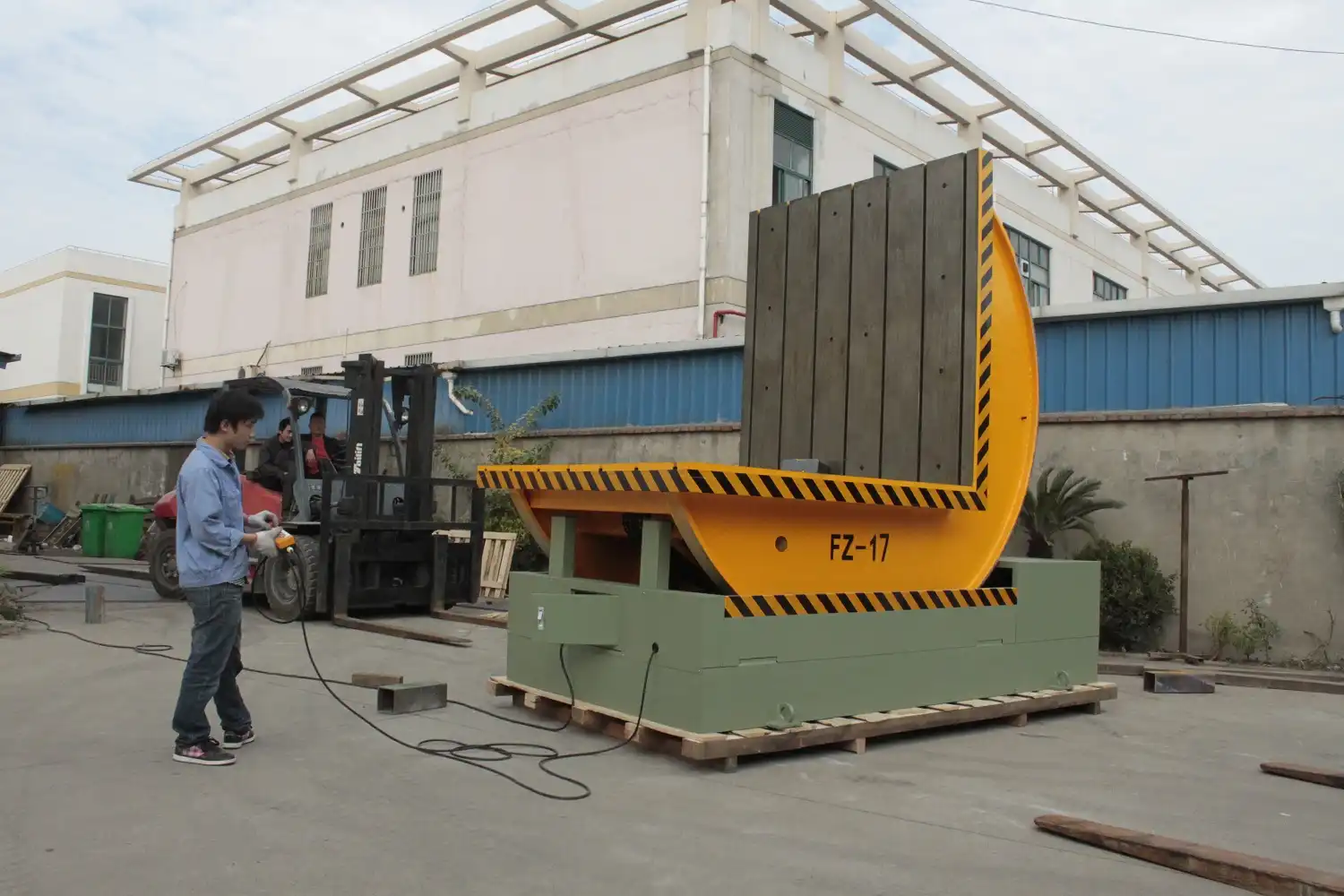
Rapid prototyping via 3D printing drastically shortens the development timeline for bespoke mold upender components. Engineers can move from a digital design to a physical, testable part—like a specialized fixture, guide rail, or support bracket—within days, not weeks or months. This allows for quick validation of fit, form, and basic function before committing to potentially more expensive final production methods or materials.
Accelerating Development Cycles Through Iteration
The core advantage of using 3D printing for prototyping mold upender components lies in its ability to facilitate rapid iteration. The traditional path often involves designing a part, commissioning expensive tooling (like molds or machining setups), waiting weeks or months for the prototype, testing it, and then potentially repeating the entire costly cycle if modifications are needed.
Additive manufacturing fundamentally changes this dynamic. The process typically follows these steps:
- Digital Design: Create the initial CAD model of the custom upender part (e.g., a conformal support pad for a uniquely shaped mold).
- 3D Printing: Send the file to an in-house or outsourced 3D printer. Depending on the part size, complexity, and printing technology (like FDM, SLA, or SLS), a physical prototype can be ready in hours or a few days. Affordable FDM printers are often sufficient for initial form and fit checks.
- Testing & Evaluation: Mount the prototype onto the mold upender. Check for correct fitment, clearance, and alignment. Perform basic functional tests – does it hold the mold securely? Does it interfere with movement? Gather feedback from operators.
- Refinement: Based on testing results, make necessary adjustments to the CAD model. Perhaps a support needs to be thicker, a curve needs modification, or mounting points need shifting.
- Reprint & Re-test: Print the revised prototype and repeat the evaluation process.
This iterative loop can be cycled through multiple times in the time it would take to get a single prototype using traditional methods. This speed allows engineers to explore more design possibilities, thoroughly validate concepts, and arrive at an optimized solution much faster.
For functional prototypes, engineers can select 3D printing materials that closely mimic the properties of the intended final part. Engineering-grade thermoplastics or even composites can be used to create prototypes robust enough for more rigorous functional testing under load, simulating real-world operating conditions more accurately. This was highlighted by Ford Motor Company’s use of FDM for creating lighter, functional assembly lift assists quickly and cost-effectively, a principle directly applicable to developing handling aids for mold upenders.
By removing the bottleneck of traditional tooling and fabrication lead times, rapid prototyping via 3D printing enables manufacturers to design, test, and deploy improved custom components for their mold upenders significantly faster, reducing development costs and accelerating the implementation of performance enhancements.
Material Innovations Driving Performance Gains
Your mold upender faces demanding conditions – heavy loads, repetitive motion, potential abrasion. Standard materials used in off-the-shelf components might wear quickly or lack the specific properties needed for optimal performance. This can lead to frequent replacements and limit the equipment’s capabilities. Advanced 3D printable materials offer a solution.
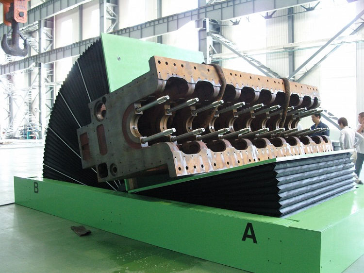
The expanding range of materials available for 3D printing, including high-strength engineering polymers, fiber-reinforced composites (like carbon fiber nylon), and various industrial metals, provides superior properties compared to many standard options. These materials enable the creation of custom mold upender parts with enhanced strength-to-weight ratios, improved wear resistance, better impact absorption, or specific chemical resilience, directly boosting durability and overall performance.
Matching Materials to Mold Upender Needs
The effectiveness of a custom 3D-printed part heavily relies on selecting the right material for the job. Different parts of a mold upender have distinct requirements, and AM offers tailored solutions:
High-Strength Polymers and Engineering Thermoplastics
For components like custom guides, protective pads, bumpers, or sensor mounts where high structural load isn’t the primary concern but toughness and wear resistance are important, engineering polymers excel.
- Nylon (PA): Offers good toughness, wear resistance, and moderate strength. Variants like PA11 or PA12 are commonly used.
- ABS: Cost-effective, good impact resistance, suitable for non-critical housings or guards.
- PETG: Combines ease of printing with good strength and chemical resistance.
- Polycarbonate (PC): High impact strength and temperature resistance, good for tougher applications.
- TPU (Thermoplastic Polyurethane): Flexible and abrasion-resistant, ideal for custom padding, bumpers, or vibration dampeners that need to conform to mold surfaces without scratching.
These materials can often be printed relatively quickly and cost-effectively using FDM or SLS technologies.
Fiber-Reinforced Composites
When higher strength, stiffness, and durability are required, potentially replacing metal parts to save weight, composites are a prime choice. These typically involve a base polymer (like Nylon) reinforced with short or continuous fibers.
- Carbon Fiber Reinforced Nylon (Nylon CF/PA-CF): Offers significantly increased strength, stiffness, and dimensional stability compared to standard Nylon. Excellent for load-bearing brackets, structural supports, or robust fixtures where weight reduction is also beneficial.
- Fiberglass Reinforced Nylon (Nylon GF/PA-GF): Provides improved strength and stiffness over standard Nylon, often at a lower cost than carbon fiber variants. Good for durable tooling or structural parts.
These materials push the performance envelope, enabling the creation of parts that are both strong and lightweight, directly impacting the upender’s dynamic performance and longevity.
Metal 3D Printing
For the most demanding applications involving high structural loads, extreme wear, or direct metal-on-metal contact, metal AM technologies like DMLS, SLM, or Binder Jetting are necessary.
- Stainless Steel (e.g., 316L): Offers good strength, excellent corrosion resistance, suitable for structural components or parts exposed to harsh environments.
- Tool Steel: High hardness and wear resistance, ideal for custom wear surfaces, locking mechanisms, or components subjected to repeated impact or abrasion.
- Aluminum Alloys: Lightweight yet strong, suitable for structural components where minimizing mass is critical, though potentially less wear-resistant than steels.
Metal AM allows for the creation of highly complex, optimized metal parts that might be impossible or prohibitively expensive to machine traditionally.
Material Properties Comparison for Upender Applications
| Material | Est. Tensile Strength (MPa) | Density (g/cm³) | Max Use Temp (°C) | Suitability for Upender Parts |
|---|---|---|---|---|
| ABS | 40 – 50 | ~1.05 | ~80-90 | Guards, non-critical fixtures, prototypes. |
| Nylon (PA12) | 50 – 60 | ~1.01 | ~100-120 | Tough guides, wear pads (moderate load), housings. |
| Nylon CF (15-20%) | 100 – 150 | ~1.15 | ~120-150 | Strong brackets, support structures, lightweight metal replacement. |
| Stainless Steel 316L | 500 – 600 | ~8.0 | >500 | Critical structural components, high-load bearings, wear surfaces. |
| TPU (Shore 95A) | ~30-40 | ~1.20 | ~70-80 | Flexible padding, bumpers, vibration dampers, conformal grips. |
(Note: Values are approximate and vary based on specific formulation and print parameters.)
By carefully selecting from this diverse palette of materials, engineers can design and print custom mold upender components optimized not just for geometry but also for mechanical performance, durability, and operational life, directly contributing to improved efficiency and reliability.
Real-World Examples and Potential Impact
While the theoretical benefits are clear, how is 3D printing actually being applied or envisioned for enhancing mold upender performance in practice? The impact stems from leveraging AM’s unique capabilities to solve specific handling challenges and optimize mechanical function.
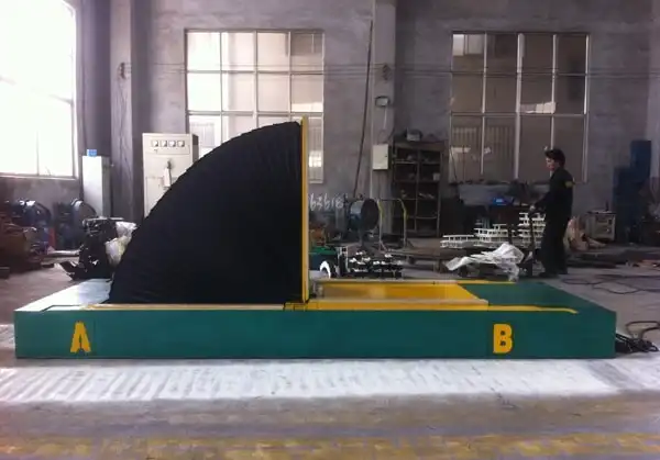
Real-world applications demonstrate 3D printing creating lighter, stronger, or application-specific parts for mold upenders. Examples include custom cradles for unusually shaped molds, optimized wear pads made from durable composites, or consolidated bracket designs reducing part count and weight. These innovations lead to measurable improvements in cycle time, reduced maintenance needs, and enhanced safety during mold handling operations.
The potential impact is significant. Consider scenarios where standard upenders struggle:
- Handling Complex Mold Geometries: A company frequently handles molds with delicate external features or non-standard shapes. Using 3D printing, they can design and produce custom-fitted cradles or support pads made from a non-marring but durable material like TPU or a specific engineering polymer. These conformal parts distribute the load evenly, prevent slippage, and protect the mold surface during tilting, something impossible with generic flat pads.
- Reducing Weight and Inertia: A large mold upender requires significant power to operate due to the weight of its tilting mechanism. By using topology optimization and printing structural components (like support arms or brackets) from high-strength composites (e.g., Nylon CF) or even lightweight metal alloys via AM, engineers can substantially reduce the moving mass. This leads to faster cycle times, reduced energy consumption, and less wear on drive components.
- Optimizing Wear Parts: Standard wear pads or guide blocks on an upender wear out quickly due to specific loading conditions. Using metal AM, engineers could design and print custom wear pads from tool steel with optimized internal cooling channels (if extreme friction were an issue) or complex surface geometries for better lubrication retention. Alternatively, tough composite materials could offer extended life over standard plastics. This reduces maintenance frequency and downtime.
- Part Consolidation and Simplification: An existing upender mechanism might use a complex assembly of multiple brackets, fasteners, and shims for a specific function. DfAM principles allow engineers to redesign this as a single, intricate 3D-printed component. This reduces assembly time, eliminates potential failure points at joints, and can often result in a lighter and stiffer overall part.
- On-Demand Spare Parts: Similar to how Mercedes-Benz envisions digital inventories for classic car parts, manufacturers using custom upender components can maintain a digital library of their designs. If a custom 3D-printed part breaks or wears out, a replacement can be printed on-demand, locally, minimizing downtime waiting for specialized parts. This increases operational resilience.
Companies like Bowman Additive Production, using HP’s Multi Jet Fusion to create complex, interlocking bearing cages with improved load capacity, showcase the potential for intricate, high-performance parts applicable to machinery components. Applying similar thinking to design custom locking mechanisms or specialized kinematic links within an upender could yield performance gains. The ability to rapidly prototype these complex ideas, as highlighted in various case studies, ensures that these innovations can be tested and implemented efficiently. The integration of AM allows for a level of customization and optimization previously unattainable, directly impacting the efficiency, reliability, and capability of mold handling equipment.
Conclusion
Ultimately, 3D printing offers a powerful pathway to enhancing mold upender performance. By enabling the creation of highly customized components tailored to specific needs, leveraging rapid prototyping for accelerated development, and utilizing advanced materials for improved durability and function, additive manufacturing provides tangible benefits. It moves beyond the limitations of standard parts, allowing for optimized designs that reduce weight, consolidate assemblies, improve mold handling accuracy, and increase operational longevity. Embracing Additive manufacturing opens the door to more efficient, reliable, and versatile mold upender operations, contributing positively to overall manufacturing productivity.

