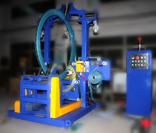
> **Executive Summary**
> Manual perimeter taping of coiled products (steel strip, wire, plastic tubing, and rubber hose) is notoriously labor-intensive, operator-dependent, and prone to tape misalignment. The automated coil side tape applicator eliminates wandering tape lines by mechanically clamping the coil in a rigid centering fixture and dispensing adhesive tape uniformly along the coil outer circumference using a constant-tension, pneumatic wipe-down assembly. Tape consumption per cycle is governed strictly by the **coil outer diameter (OD)** multiplied by **π**, plus an engineered **sealing overlap** (typically 50–100 mm).

<iframe width="940" height="535" src="https://www.youtube.com/embed/5AyGF2JU1LY" frameborder="0" allow="accelerometer; autoplay; clipboard-write; encrypted-media; gyroscope; picture-in-picture; web-share" referrerpolicy="strict-origin-when-cross-origin" allowfullscreen></iframe>

---

<h2 id="table-of-contents">Table of Contents</h2>

<ul>
<li><a href="#video">System Overview & Structural Layout</a></li>
<li><a href="#how-it-works">Sequence of Operation and Motion Profile</a></li>
<li><a href="#tape">Tape Consumption and Yield Calculation</a></li>
<li><a href="#safety">Control Architecture and Safety Compliance</a></li>
<li><a href="#selection-checklist">Selection Checklist for a Coil Side Tape Applicator</a></li>
<li><a href="#engineering-faq">Engineering FAQ</a></li>
<li><a href="#next-step">Next Steps & System Engineering</a></li>
<li><a href="#related-reading">Related Reading</a></li>
<li><a href="#sources">Sources</a></li>
</ul>

<h2 id="video">System Overview & Structural Layout</h2>

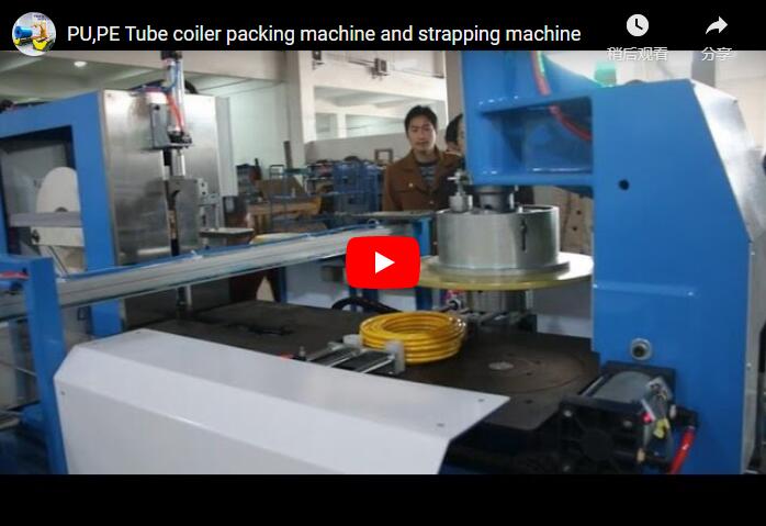
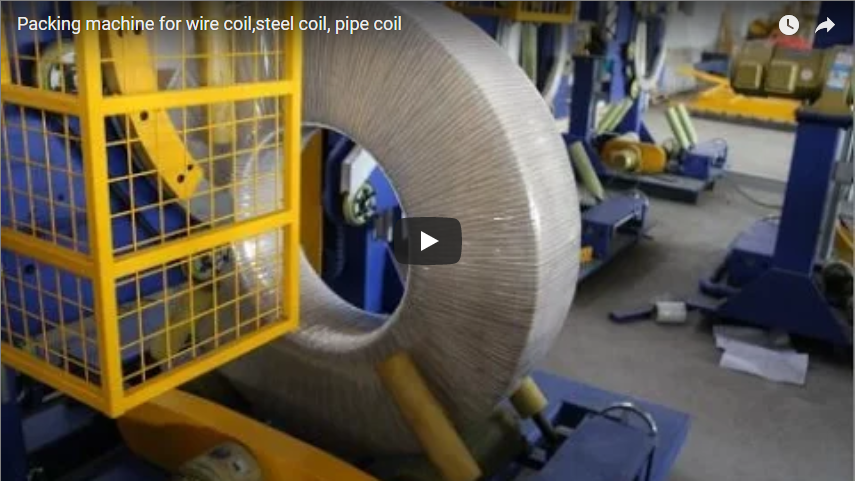
The automated coil side tape applicator is engineered as a standalone or inline packaging cell designed to secure the outer tails and circumferential wraps of industrial coils. The machine structure integrates three core mechanical assemblies:

1. **Centering and Clamping Station**: Heavy-duty pneumatic or hydraulic clamp arms equipped with non-marking polyurethane contact pads align the coil to the exact spindle centerline, preventing axial runout or slippage during taping.
2. **Circumferential Tape Dispensing Head**: A dedicated tape applicator head integrates a low-inertia payout spool, an adjustable friction-brake tensioning assembly, guide rollers, and a soft-pneumatic pressure roller that wipes the tape firmly onto the coil's outer face to eliminate air entrapment.
3. **Structural Safety & Operator Interface**: The station is enclosed within powder-coated perimeter perimeter safety mesh guards, interfaced with safety interlocks. A machine-mounted operator station integrates industrial push buttons, a multi-tier LED stack tower (red/amber/green status indication), and an intuitive HMI touchscreen for recipe adjustments and diagnostic fault logging.

<h2 id="how-it-works">Sequence of Operation and Motion Profile</h2>

The system automates the coil transfer, positioning, taping, and discharge cycle to deliver repeatable tape tension and uniform edge alignment across high-throughput lines.

| Cycle Phase | Functional Mechanism & Action | Target Duration (Nominal) |
|---|---|---|
| **Infeed & Indexing** | The coil is transferred from the upstream conveyor to the central taping cradle. | ~8 s |
| **Clamping & Alignment** | Dual side-clamping jaws actuate radially to centralize and mechanically lock the coil OD. | ~8 s |
| **Taping & Wipe-down** | The coil rotates (or the tape head tracks the perimeter) under controlled web tension; the pneumatic guide roller applies consistent contact pressure to lay down and wipe the tape. | ~8–12 s |
| **Cut & Discharge** | A high-speed serrated cutter severs the tape web; clamp jaws retract, and the powered roller bed transfers the taped coil downstream. | ~10–12 s |

Mechanical rigidity during the clamping phase prevents coil eccentric wobbling, ensuring the tape edge maintains an axial positioning accuracy within ±2.0 mm across every unit processed.

<h2 id="tape">Tape Consumption and Yield Calculation</h2>

Tape usage per coil is directly proportional to the coil circumference, governed by the formula:

`Total Tape Length per Coil (L_tape) = (π × D_coil) + L_overlap`

Where:
- `D_coil`: Outer diameter of the coil (m)
- `π`: Mathematical constant (approximately 3.1416)
- `L_overlap`: Tail overlap required to guarantee adhesion under storage/handling tension (standard engineering default: 0.05 m to 0.10 m)

### Engineering Worked Example:

| Engineering Parameter | Metric Value | Imperial Value |
|---|---|---|
| Nominal Coil Outer Diameter (`D_coil`) | 1,000 mm (1.0 m) | 39.37 in |
| Circumferential Perimeter (`π × D_coil`) | 3,142 mm (3.142 m) | 123.7 in |
| Designed Lap Overlap (`L_overlap`) | 80 mm (0.08 m) | 3.15 in |
| **Total Tape per Finished Coil** | **3.222 m** | **126.85 in** |
| Standard Tape Roll Length (Illustrative) | 66.0 m | 216.5 ft |
| **Theoretical Yield per Roll** (66.0 m ÷ 3.222 m) | **20 finished coils** | **20 finished coils** |

*Note: For high-volume automated lines, machine-grade tape rolls (e.g., 500 m to 1,500 m jumbo rolls) are recommended to reduce downtime caused by manual roll changeovers.*

<h2 id="safety">Control Architecture and Safety Compliance</h2>

The machine's clamping arms and high-speed tape cutting blade present distinct mechanical pinch-point and cutting hazards. The following safety architecture is implemented to ensure global industrial compliance:

- **Perimeter Guarding**: Interlocked yellow steel mesh panels prevent personnel access to pinch zones during automatic cycling. Opening any access door triggers a Category 0 safety stop via dual-channel safety relays.
- **Lockout/Tagout (LOTO)**: Certified pneumatic dump valves and lockable electrical main disconnects allow maintenance teams to de-energize and exhaust residual mechanical/air pressure before tape spool replenishment or blade maintenance.
- **Harmonized Standards**:
  - **ISO 12100:2010**: Applied for systematic machinery risk assessment and risk reduction design.
  - **EN 415-10:2014**: Covers safety requirements for automated and semi-automated packaging machines.
  - **EN ISO 13849-1**: Implemented for performance level (PLr = d) safety control circuits.

<h2 id="selection-checklist">Selection Checklist for a Coil Side Tape Applicator</h2>

Before specifying a coil side taping cell, confirm the following technical parameters with your packaging engineering team:

- **Coil Dimensional Boundaries**: Minimum and maximum coil outer diameter (OD), inner diameter (ID), and face width.
- **Coil Weight & Material Spec**: Mass range (kg), surface finish (dry, oiled, cold-rolled, rubber, PE jacket), and temperature at station infeed.
- **Tape Substrate & Adhesion Profile**: Filament-reinforced tape, PVC, BOPP, or masking; web width (e.g., 25 mm, 50 mm, 75 mm); core diameter (76 mm standard).
- **Taping Position**: Single centerline band, outer edge overlap, or multiple parallel passes.
- **Cycle Time Requirement**: Target parts per minute (PPM) or parts per hour (PPH) required by upstream slitting/coiling stations.
- **Upstream/Downstream Integration**: Conveyor interface height, driven roller vs. gravity, and upstream PLC handshaking (Profinet, Ethernet/IP, or volt-free dry contacts).

<h2 id="engineering-faq">Engineering FAQ</h2>

**Q: How does the machine ensure the tape adheres firmly without air bubbles?**
A: The taping head incorporates a spring-cushioned or low-pressure pneumatic wipe-down roller with a high-durability elastomer sleeve. As the coil indexes, this roller exerts an adjustable force (typically 0.2 to 0.4 MPa air supply regulated) directly across the tape backing, forcing out trapped air and ensuring 100% wet-out of pressure-sensitive adhesive.

**Q: Can this machine apply reinforced filament tape to heavy steel coils?**
A: Yes. The tape head is built with heavy-duty blade assemblies (air-actuated shear blades or heated guillotine cutters) capable of cleanly severing high-tensile fiberglass filament tape and polypropylene strapping tape without fraying.

**Q: What happens when the tape roll reaches its end?**
A: A photoelectric or optical contrast sensor tracks the spool diameter. An amber stack light warning and HMI message alert the operator at low roll level, and the machine gracefully finishes the current coil and halts before cycling without tape.

**Q: Can the station accommodate varying coil diameters sequentially?**
A: Yes. The clamping cylinder stroke and optical sensing system automatically compensate for differing coil diameters within the engineered minimum and maximum window, requiring zero mechanical changeover between standard production batches.

<h2 id="next-step">Next Steps & System Engineering</h2>

To integrate an automated coil side tape applicator into your finishing line:

1. **Submit Product Data**: Send your coil envelope dimensions (OD/ID/Width/Weight), tape specifications, and general layout drawings to **info@fhopepack.com**.
2. **Engineering Layout Review**: Receive a customized 2D/3D footprint layout and technical proposal within **48 hours**, including guaranteed cycle times and overlap control specs.
3. **Technical Line Assessment**: Coordinate with our project engineering team for a physical line audit or virtual factory acceptance review to verify interface signals and line speeds.

<h2 id="related-reading">Related Reading</h2>

- [Steel Coil Wrapping Machine Solutions](https://www.fhopepack.com/Steel-coil-wrapping-machine/)
- [Video: Steel Wire and Pipe Coil Packaging Lines](https://www.fhopepack.com/videos/coil-wrapping-machine-and-pipe-coil-packing-machine-for-steel/)
- [Automated Profile Taping, Transfer, and Horizontal Wrapping Systems](https://www.fhopepack.com/videos/automated-aluminum-profile-taping-transfer-horizontal-wrapping-line/)

<h2 id="sources">Sources</h2>

- Technical Equipment Specifications: FHOPE Machine R&D Archive, Updated 2026-10-04
- Motion Profile & Field Trials: [Automated Coil Taping Unit in Operation (YouTube)](https://www.youtube.com/watch?v=5AyGF2JU1LY)
- International Safety Compliance: [ISO 12100:2010 Machinery Safety Risk Assessment](https://www.iso.org/standard/51528.html)
- Packaging Machinery Standards: [EN 415-10:2014 Safety Requirements for Packaging Machines](https://www.nen.nl/en/nen-en-415-10-2014-en-191845)

<p><strong>Last reviewed:</strong> 2026-10-04</p>