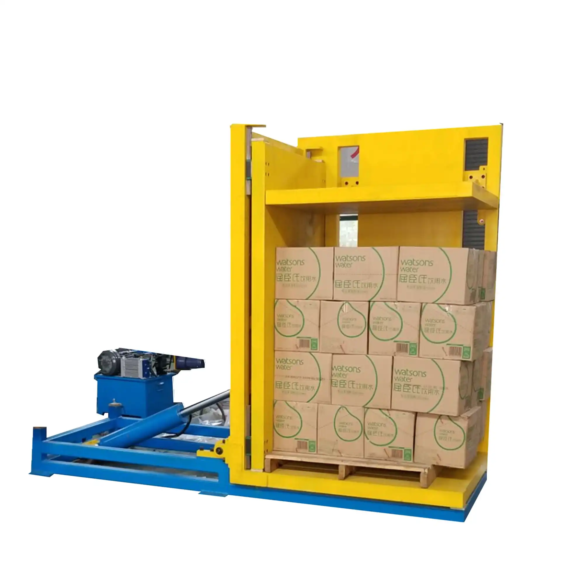
Engineering Mechanics: Overturning Moments and Clamping Forces
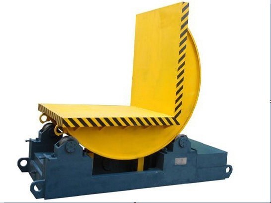
Sizing stationary pallet inverters requires calculating the dynamic overturning moment generated during intermediate rotation angles and determining clamping pressures that prevent cargo slippage without damaging carton walls.
 Rotation Axis (Center of Rotation)
                                     O
                                    /|
                                   / |
                                  /  |
                    R_CG         /   | d_CG(theta)
                                /    |
                               *     v
                       Center of Gravity (CG)
                       Load Mass = m_total
What Sets the Peak Turnover Load
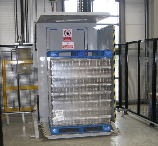
The cradle is rated on the worst angular position, not on the rest position. With a two-ton cargo load and a rotating carriage of roughly 1.2 t, the assembly carries about 3.2 t through the turn. The composite centre of gravity sits above the rotation axis and slightly off-centre whenever a stack is not perfectly placed; as the cradle rotates, that point swings outward and the horizontal lever arm grows until it peaks partway through the sweep. FHOPEPACK locates that peak before selecting the drive, then multiplies the static moment by a dynamic service factor to cover angular acceleration, hydraulic friction, and cold-oil viscosity. For a representative two-ton application the static overturning moment comes out near 8.2 kN·m and the dynamic value near 11.1 kN·m, which the supplied power pack covers with reserve.
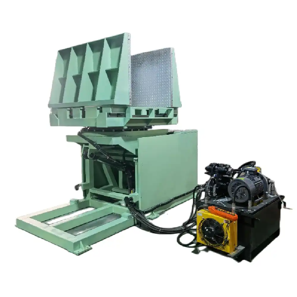
The electro-hydraulic power pack provides torque reserve through high-ratio mechanical drives or dual-cylinder rack assemblies, sustaining smooth rotation across the entire sweep.
How Clamp Force Is Set Against Slippage
A load held only by gravity slides once the cradle passes the point where the friction between cartons and clamp faces can no longer carry the vertical component of its own weight. The clamp force therefore has to satisfy static friction equilibrium at the steepest part of the turn, with the load shared between the two opposing faces.
For the two-ton rating, the weight of the cargo resolves to roughly 19.6 kN. With a conservative static friction coefficient of 0.30 between dry timber or corrugated board and the clamp platen, the two faces together must supply about 32.7 kN of normal force, and a structural factor of 1.25 lifts the target to roughly 40.9 kN — about 4.2 tonnes-force split across the pair.
Surface pressure follows from the contact area. On a standard 1200 mm x 1000 mm pallet with effective contact over about 70 percent of the upper surface, that target lands near 48.7 kPa, low enough for multi-wall corrugated cases and woven bags to survive the turn while friction still holds the stack square.
This controlled surface pressure prevents crushing of corrugated boxes while maintaining positive friction to stabilize the cargo stack during turnover.
How Two Contact Faces Change the Pressure Map
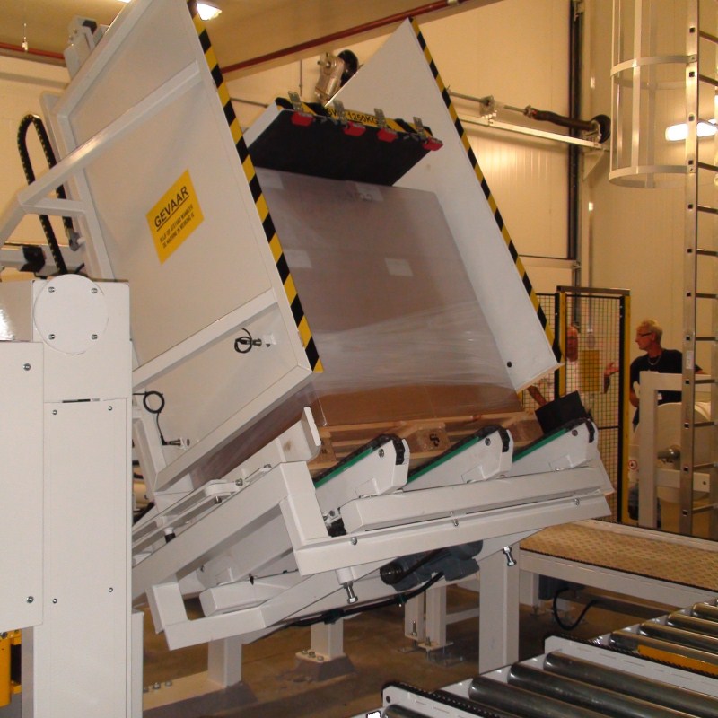
With one platen, the whole holding force enters the stack from a single face and has to be transmitted down through the layers to the fixed deck. With two platens closing toward each other, the force enters from both ends and the middle layers carry less of it — which is why a two-clamp machine can hold a taller stack without raising the pressure on the weakest layer.
The pressure map across the top face is not uniform either way. Platen deflection under load means the centre of the plate bears harder than the edges on a stiff deck, and the reverse happens on a compliant deck that settles under the plate. That is why the contact face is checked for flatness rather than only for area, and why a bolted liner is used as a replaceable interface rather than welding a facing onto the platen.
Where the stack is uneven — cartons stacked to different heights, bags that have settled in storage — the highest points take the first contact and the pressure concentrates there until the rest of the face catches up. Two platens halve that concentration because each face only has to reach halfway through the stack, but they do not eliminate it. Loads with significant height variance are the case where an articulated or segmented platen earns its cost.
Structural Fabrication and Shop Floor Integration
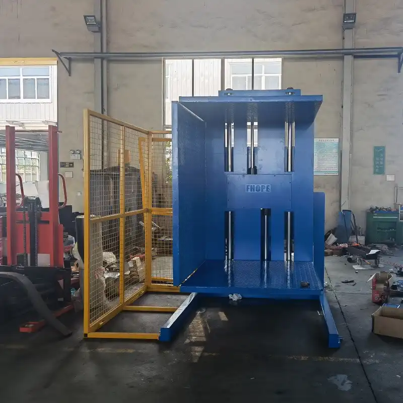
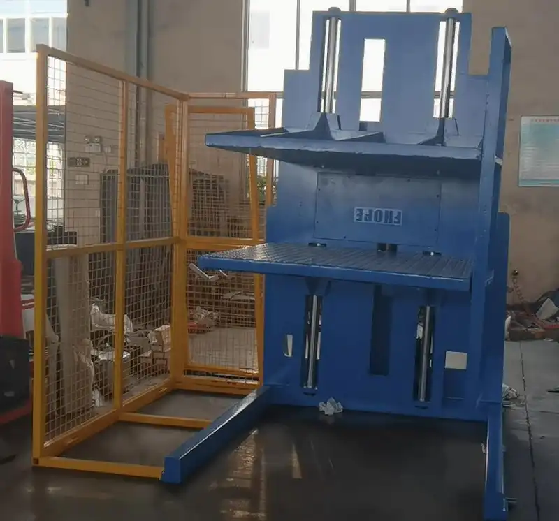
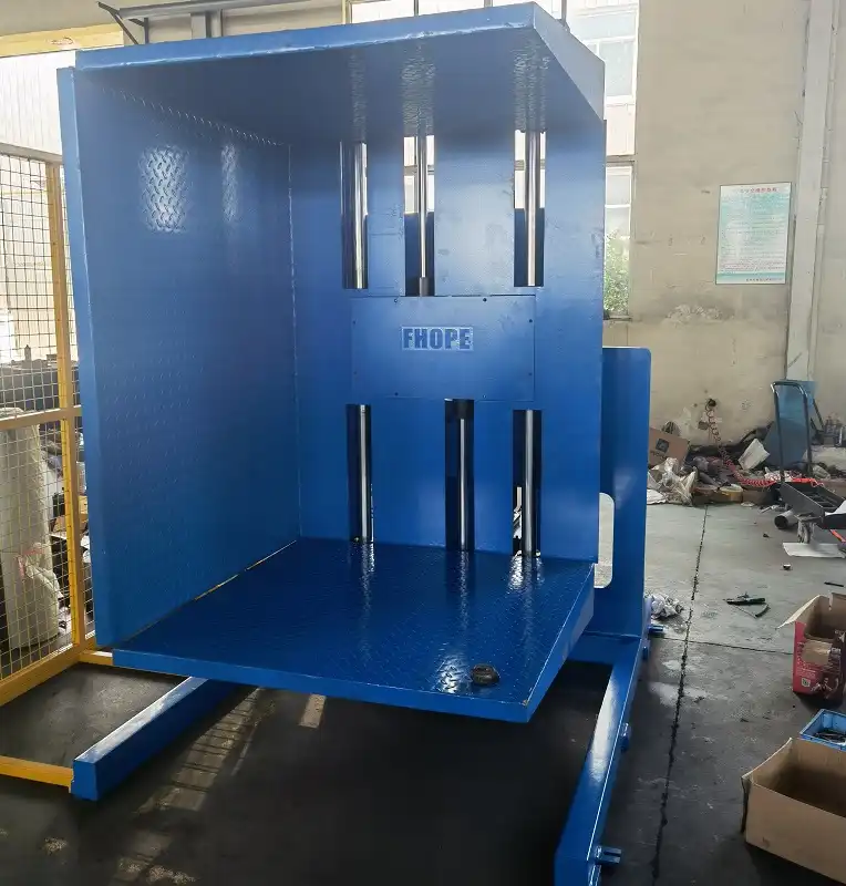
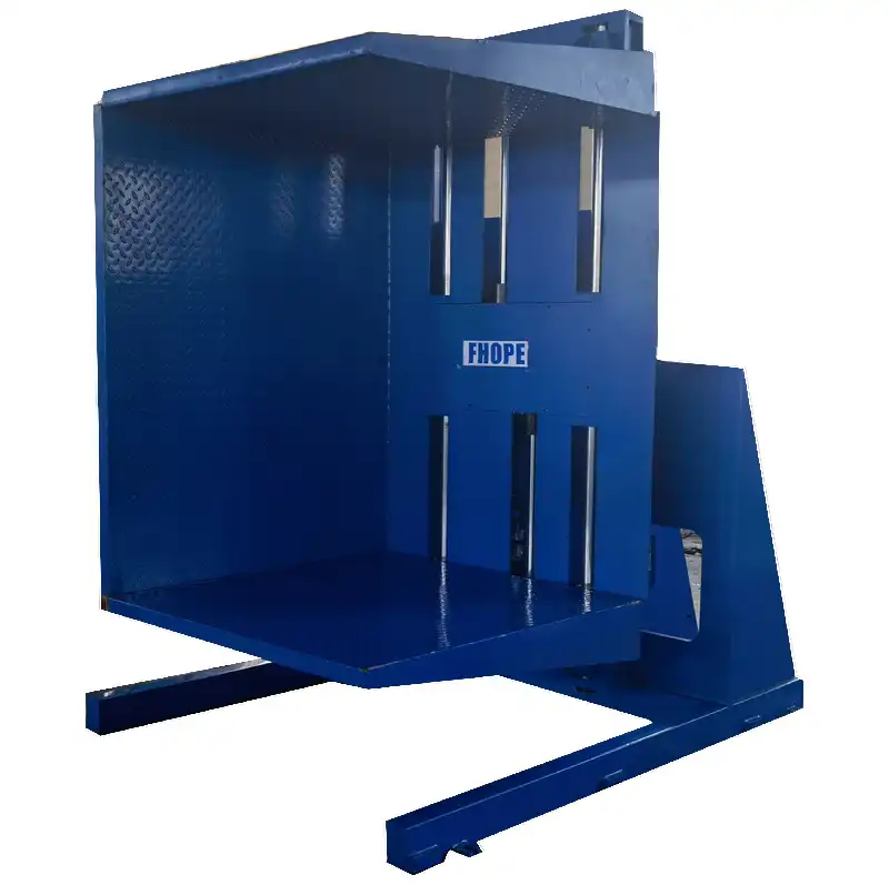
The FPFZ-C02 is built for continuous multi-shift duty, so the fabrication choices are driven by how many turns the frame will see in a year rather than by the product being handled.
Structural Frame and Foundation Anchor Protocol
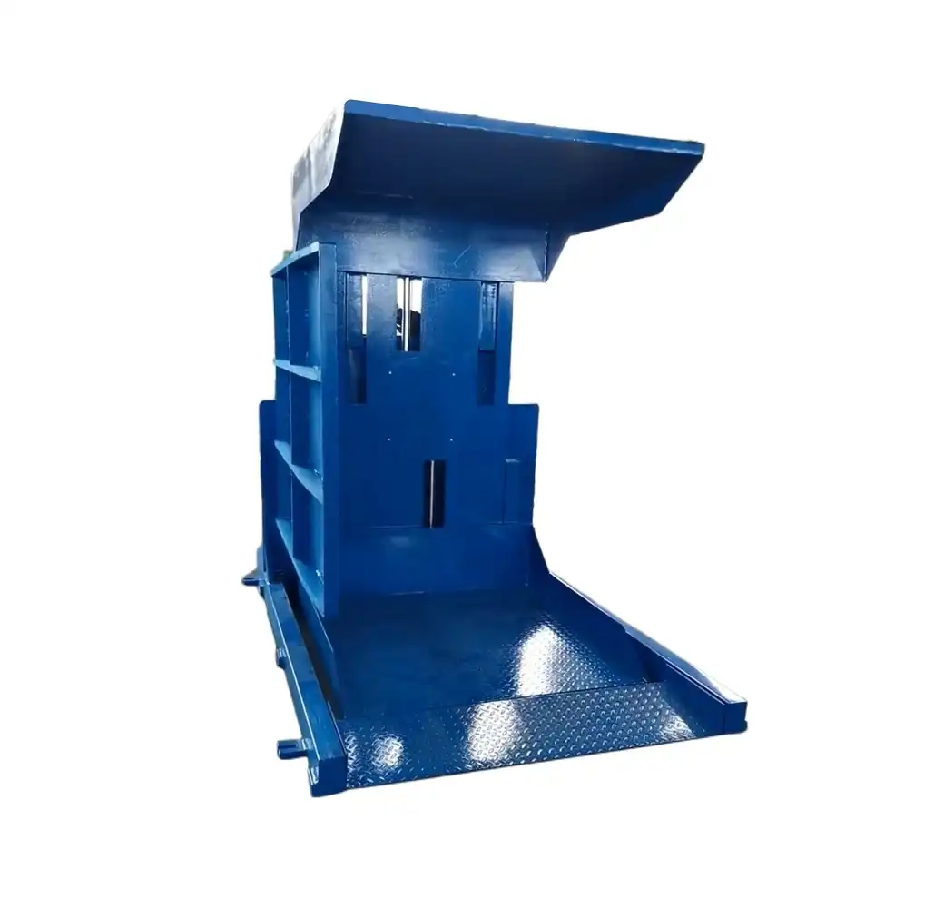
The core support structure uses profile-welded A3 structural steel (equivalent to ISO 630 E235B / ASTM A36) to resist repeated torsional cycles. What governs its section size is not the rated load alone but the torsional case: a stack placed off the cradle centreline loads one side of the frame harder on every turn, so the frame is checked against the customer's actual load geometry rather than against a nominal figure.
The machine must be secured to a solid concrete slab using heavy-duty chemical or mechanical expansion anchor bolts. Floor anchoring prevents frame walking, absorbs dynamic tipping moments as the rated load swings through horizontal orientations, and isolates operational vibrations from surrounding packing machinery.
Hydraulic and Electrical System Configuration
The hydraulic power unit uses an oil-immersed gear pump coupled to high-pressure manifold blocks:
-
Pilot kumandalı çek valfler: Mounted directly onto the clamp cylinder ports, locking pressure in place if electrical power or hydraulic feed lines drop.
-
Counterbalance holding valves: Counter dynamic runaway torque when turning loads past the 90-degree balance point.
-
Kontrol ünitesi: IP54-rated, with the control circuit stepped down and isolated from the motor supply so that a remote pendant and the pedestal station share one safety circuit.
Controls are split between an anchored pedestal control station located outside the perimeter hazard zone and a wireless remote transmitter. Forklift operators can initiate clamping, 180-degree rotation, and unclamping sequences directly from the forklift seat.
To evaluate complete turn-key conveyor lines and automated packaging systems, review our pallet-inverter-manufacturer üretim yetenekleri.
Safety Standards, Risk Mitigation, and Maintenance Protocols
Stationary pallet inverters handle high kinetic energies and dynamic turning moments. FHOPEPACK designs the FPFZ-C02 around harmonized international safety and machinery standards.
Harmonized Design Standards Matrix
-
EN-1570 1: Safety requirements for lifting tables and industrial positioning equipment.
-
EN ISO 12100Makine güvenliği — Tasarım, risk değerlendirmesi ve risk azaltmaya yönelik genel prensipler.
-
EN-60204 1: Electrical equipment of industrial machines — Safety and control wiring compliance.
-
ISO-13849 1: Safety-related parts of control systems (Engineered to Performance Level d, Category 3 architecture).
-
ISO 4413: Hydraulic fluid power — General rules and safety requirements for systems and components.
Plant Safety Systems and Perimeter Protection
-
Integrated perimeter fencing: High-visibility welded mesh panels installed around three sides of the turnover radius.
-
Class 4 optical safety light curtains: Mounted across the forklift loading entryway; interrupting the beam during turnover halts motion in under 120 milliseconds.
-
Acil durdurma butonları: Placed on the main electrical enclosure, wireless transmitter, and stationary pedestal.
Planlı Bakım Protokolü
-
Daily / Pre-Shift: Visually check clamping faces for dunnage debris; confirm safety light curtains and emergency stop buttons function.
-
Weekly (Every 50 Operating Hours): Inspect hydraulic hoses and swivel joints for micro-abrasions, fluid weeping, or fittings loosening; verify hydraulic reservoir fluid level.
-
Monthly (Every 200 Operating Hours): Lubricate clamping carriage guide columns and pivot bearings using high-pressure lithium grease; check mounting anchor bolt torque.
-
Annual (Every 2000 Operating Hours): Complete hydraulic fluid flush; replace 10-micron return line filter cartridges; run pressure-drop tests on load-holding check valves.
RFQ Engineering Input Matrix and Service Level Agreement
Incomplete operational specifications cause engineering delays and mismatched machinery sizing. To receive a detailed proposal for the FPFZ-C02, provide the technical parameters outlined below:
The parameters that decide the clamp setting and the frame section are the ones the product page cannot supply, because they belong to your product rather than to the machine:
|
Technical RFQ Parameter
|
Why It Changes the Build
|
|
Packaging crush limit
|
Allowable surface pressure in kPa sets the relief valve ceiling and the platen contact area.
|
|
Product geometry and stability
|
Cartons, bulk bags, drums and sheet stacks each need a different contact face and friction facing.
|
|
Layer restraint method
|
Strapping, stretch wrap, trays or slip sheets decide whether the load survives the turn without containment.
|
|
Off-centre load habit
|
How far the stack sits from the cradle centreline in normal operation drives the torsional check on the frame.
|
|
Güvenlik entegrasyonu
|
Existing line interlocks, gate positions and perimeter fencing decide how the machine ties into site safety logic.
|
Engineering Service Level Agreement (SLA)
24
24-Hour Review
When you submit a complete RFQ with verified load footprints, package heights, and gross weights, our engineering team completes turning moment and hydraulic clamping checks within 24 hours.
48
48-Hour GA Layout
FHOPEPACK delivers a machine General Arrangement (GA) drawing in 2D/3D (DWG/STEP) within 48 hours, highlighting base anchoring requirements, dynamic turnover clearance boundaries, and recommended perimeter safety fencing footprints.
What Sets Practical Throughput on a Two-Clamp Station
The turnover time is published on the product page, but it is not the number that decides how many pallets a shift can exchange. A forklift-fed station spends most of its time waiting for the truck, not turning the load.
Three intervals sit outside the rotation: the truck positioning and setting the load down, the operator removing the old pallet and fitting the new one, and the truck clearing the station before the next load arrives. On a two-clamp machine the swap interval is short because both faces are open once the cradle locks and the clamp relaxes, but the truck intervals depend on the building — aisle width, racking clearance, and whether the machine can be served from both sides.
That is why throughput planning starts from the truck cycle rather than from the machine cycle. If the aisle only allows one truck at a time, adding a second machine does not double the rate; it doubles the queue. Where the site can serve from both sides, the station can be worked as a through-flow and the truck intervals overlap with the rotation, which is usually the cheaper capacity gain than a second unit.
Questions From Dual-Clamp Buyers
How is the clamp pressure set for a fragile product?
Clamping force is regulated by a proportional relief valve rather than by a fixed mechanical stop. The operator sets the threshold on the HMI against the product's crush limit, and a pressure switch confirms the target has been reached before rotation is enabled. Once set, pilot-operated check valves hold that pressure through the turn, so the platen cannot creep open under load.
When does a single clamp replace the two-clamp arrangement?
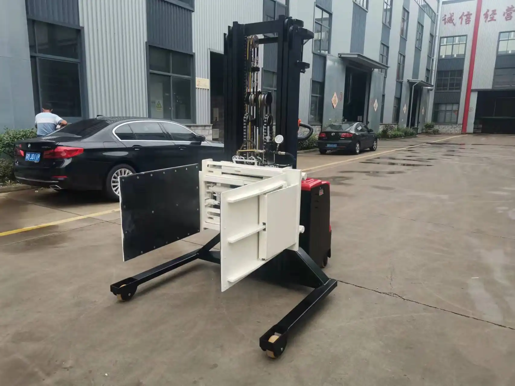
When the load is rigid and fully enclosed — sealed drums, strapped crates, palletised blocks — a single top platen with a fixed lower deck is enough, and the simpler frame costs less to maintain. The two-clamp layout earns its place when the stack is tall relative to its footprint, when cartons or bags sit at the top of the load, or when the load must be held from both faces to keep it square through the rotation.
What wears first on the clamping assembly, and how is it replaced?
The platen contact faces and the guide wear pads take the abrasion. Bolt-on HDPE or polyurethane liners can be unbolted and replaced on the shop floor without removing the carriage; on timber-contact duties a hardwood facing is sometimes fitted instead. Guide pads are shimmed to a clearance that keeps the platen square as it travels, and the cylinder rod seals are the next wear item on the clamping stroke.
Sonuç
Send the pallet footprint, stack height, gross weight, and the product's crush limit. FHOPEPACK sizes clamp force against that limit, sets the relief pressure for the supplied power pack, and returns the layout drawing with the clamping sequence documented for operator training.