Samenvatting
A commercial hose coil must strictly comply with three physical packaging criteria: target winding length, controlled inside diameter (ID), and maximum outside diameter (OD) constrained by secondary shipping cartons or pallet footprints. The automatic hose coil making machine integrates cantilevered collapsible winding drums, servo-driven traversing pitch synchronization, high-speed rotary cutting, and inline film packaging. By automatically winding, indexing, and securing each bundle directly behind the extrusion line, the system guarantees repeatable volumetric coil dimensions, prevents corrugated wall deformation, and eliminates manual packaging bottlenecks.
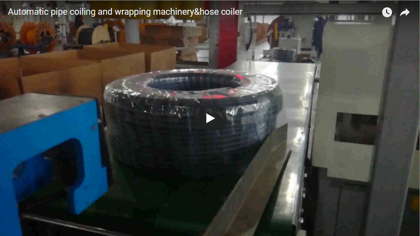
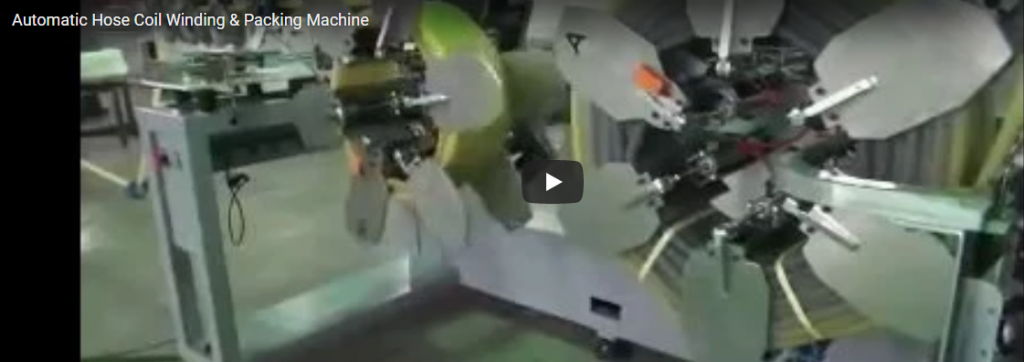
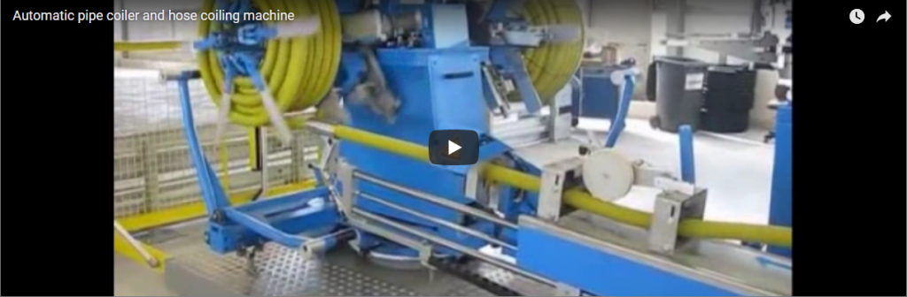
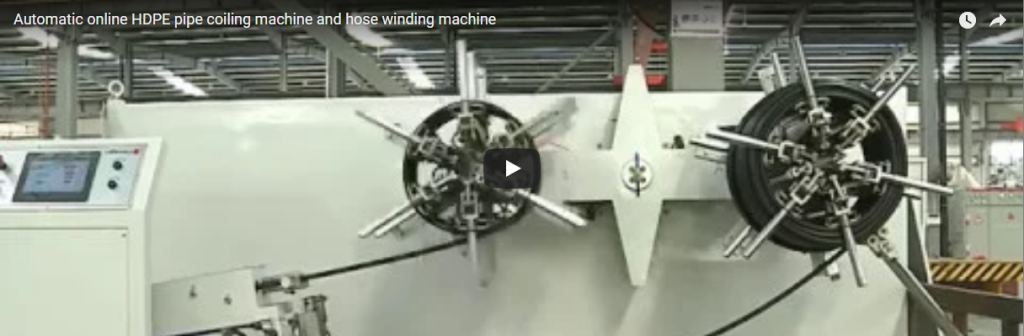
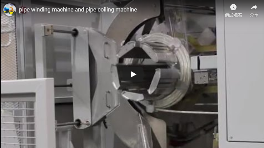
Automated dual-drum coiler winding flexible corrugated hose with precision servo traverse, followed by integrated orbital film stretch-wrapping and pneumatic mandrel collapse for non-destructive discharge.
Inhoudsopgave
- What Sets Coil Size: Core Mechanical Elements
- Coil Making Sequence: Extrusion Line Integration
- Kinematic Coil Length Calculations & Nesting Factors
- Standard Machine Technical Specifications
- Mandrel Release & Structural Integrity Control
- Procurement & Line Integration Checklist
- Industrial Safety Standards & Compliance
- Veelgestelde vragen over techniek
- Technical RFQ & Specification Submissions
- Gerelateerde verpakkingsoplossingen
- Reference Standards
What Sets Coil Size: Core Mechanical Elements
A hose coiling machine establishes coil geometry through four synchronized mechanical and automation subsystems:
+---------------------------------------------------------------+
|                   EXTRUSION / FEED INFEED                     |
+---------------------------------------------------------------+
                               |
                               v
+------------------+   +-------------------+   +----------------+
|  EXPANSION CORE  |   |  FLANGE CLEARANCE |   | SERVO TRAVERSE |
|   (Governs ID)   |   |  (Governs Width)  |   | (Controls Pitch|
| Pneumatic wedges |   | Adjustable plates |   |  & Layer Level)|
+------------------+   +-------------------+   +----------------+
                               |
                               v
+---------------------------------------------------------------+
|      OPTICAL ENCODER COUNTER (Sets Metres & Resulting OD)     |
+---------------------------------------------------------------+- Collapsible Core Diameter (Coil ID): Set by pneumatic expanding segments or mechanically locked mandrel wedges. Expanding segments ensure a rigid winding perimeter during winding, then retract radially to clear the internal diameter without scraping internal corrugations.
- Flange Spacing (Coil Width): Symmetrical side flanges retain the lateral boundary of the coil. Adjusting flange spacing accommodates specific commercial coil face widths or pre-formed packaging cartons.
- Length Counter (Coil OD): High-precision measuring wheels equipped with dual-channel optical encoders read linear displacement. Once the target meterage is reached, the drive halts the coiling spindle, determining the final outer diameter based on hose wall thickness and nesting behaviour.
- Servo-Driven Traverse Unit: A ball screw driven by an AC servo motor guides the infeed hose smoothly across the drum face. The traverse pitch matches the nominal hose outer diameter (plus a minor nesting offset), preventing irregular humps, edge crossover, or sudden layer collapses.
Adjusting the expandable core base and flange width allows one machine to process diverse product lines, from small-diameter conduit to heavy industrial delivery hoses.
Coil Making Sequence: Extrusion Line Integration
Continuous extrusion lines demand continuous take-up. The automated dual-station coiling cycle executes in six distinct phases:
- Klemmen: The extruded hose front end passes through safety guides and is secured by an automatic mechanical or pneumatic clamp seated within the drum core.
- Synchronized Coiling & Traversing: The main variable frequency drive (VFD) accelerates the drum to line speed, governed by an inline dancer accumulator loop to maintain constant line tension. The servo-driven traverse sweeps back and forth between flanges, laying uniform adjacent passes.
- Deceleration & Length Cutoff: Upon reaching the programmed meter count, the dancer takes up temporary line buffer accumulation while the drum slows. A guided pneumatic guillotine or rotary blade makes a square cut across the hose profile.
- Tail Securing: The trailing end is held against the wound bundle via external pneumatic contour press rollers to prevent elastic unraveling.
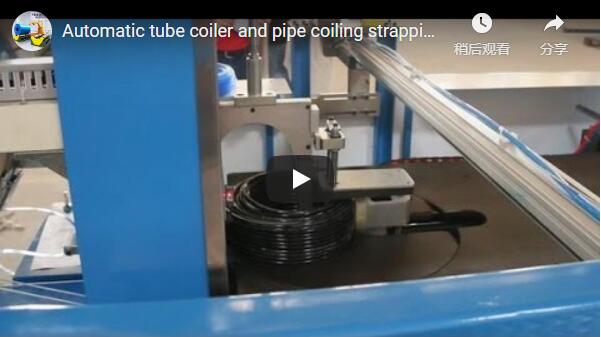
- Inline Strapping or Stretch Wrapping: While firmly held on the rigid drum, the coil is either bound through integrated flange slots with PP/PET strapping, or passed through an orbital wrapping ring that applies protective stretch film around the coil circumference.
- Core Collapse & Discharge: The drum segments collapse radially inward by 20–40 mm. An integrated stripping pusher plate or tilting ejector advances the wrapped bundle onto a downstream roller conveyor, table, or sorting station.
Kinematic Coil Length Calculations & Nesting Factors
Theoretical coil geometry relies on concentric layer calculations. Packaging engineers must account for the cross-sectional geometry of the hose when calculating coil OD and box sizing:
Turns Per Layer ≈ Coil Width ÷ Hose Outer Diameter (OD)
Totaal aantal lagen ≈ (Coil OD − Coil ID) ÷ (2 × Hose OD)
Lengte van de spoel ≈ π × ((Coil OD + Coil ID) ÷ 2) × Turns Per Layer × Total Layers
Voorbeeld van een technische berekening
- Slangspecificaties: Corrugated PE hose, nominal OD = 20 mm
- Drum Tooling: Inner Diameter (ID) = 350 mm; Maximum Coil Outer Diameter (OD) = 500 mm; Usable Width between Flanges = 200 mm
Turns Per Layer = 200 mm ÷ 20 mm = 10 turns
Totaal aantal lagen = (500 mm − 350 mm) ÷ (2 × 20 mm) = 150 mm ÷ 40 mm = 3.75 layers
Gemiddelde draaicirkel = (500 mm + 350 mm) ÷ 2 = 425 mm
Mean Circumference = π × 425 mm ≈ 1,335.18 mm
Theoretical Pack Length ≈ 1,335.18 mm × 10 × 3.75 ≈ 50,069 mm (50.07 m)
Nesting Factor Caveat: Standard smooth-wall hoses sit in stacked layers. Flexible corrugated tubes tend to nest between the ridges of the preceding layer under winding tension. This nesting reduces effective pitch by 5% to 12%, yielding a smaller final coil OD for a given length. A baseline test coil is always wound during commissioning to fine-tune the PLC servo traverse pitch offset and encoder scale.
Standard Machine Technical Specifications
The coiler is engineered for continuous production environments matching high-speed extruders, corrugators, and rewinding stations.
| Specificatie Parameter | Metrische waarde | Imperial / Operating Value |
|---|---|---|
| Binnendiameter spoel (ID) | 350–550 mm (instelbaar) | 13.8-21.6 inch |
| Buitendiameter van de spoel (OD) | 500–800 mm max. | 19.7-31.5 inch |
| Spoelbreedtebereik | 150 – 300 mm | 5.9-11.8 inch |
| Maximaal spoelgewicht | 5-35 kg | 11.0-77.2 lbs |
| Operating Line Speed | 1–60 m/min | 3.3–196.8 ft/min |
| Spindle Drive Configuration | Dual Cantilever Stations | Continuous auto-indexing |
| Totaal aangesloten vermogen | 4.5 kW | 3-Phase 380V/480V 50/60 Hz |
| Vereiste pneumatische voeding | 0.6–0.7 MPa | 6–7 bar (dry, filtered air) |
| Packaging Consumable Match | Orbital LLDPE Film or PP Strap | Film: 17–25 µm; Strap: 12–13 mm |
Mandrel Release & Structural Integrity Control
High winding tension causes elastic polymer hoses (PVC, PE, EVA, PU) to grip the rigid winding drum tightly. Attempting to force an uncollapsed coil off a fixed drum shears the inner corrugated profiles and destabilizes side alignment.
To maintain coil integrity during discharge, the coiler uses a three-tier release mechanism:
[ Winding Phase ]                  [ Release Phase ]
======================             ======================
|  Expanded Segments |             | Retracted Segments |
|  [=== Core OD ===] |    ===>     | [ -20 mm Stroke -] |
| (Tight Hose Grip)  |             | (Radial Gap Opens) |
======================             ======================
                                              |
                                              v
                              [ Pneumatic Stripper Plate ]
(Ejects wrapped coil cleanly)- Radial Mandrel Retraction: A centralized pneumatic cylinder or toggle linkage collapses the four-segment drum core radially inward, freeing the inside coil diameter from surface shear.
- Inline Outer Stabilization: The coil is bound with tensioned PP strap or orbitally wrapped with LLDPE stretch film prior to drum retraction. This retains hoop tension within the coil bundle rather than relying on core friction.
- Guided Pusher Strip: An integrated rear stripping plate advances across the collapsed mandrel face via low-pressure pneumatic cylinders, gently pushing the bundle onto downstream inspection zones without human operator intervention.
Procurement & Line Integration Checklist
Confirm the following operating parameters to tailor drum segmentation, traversing rates, and packaging stations to your line:
- Hose Cross-Section Profile: OD, wall thickness, corrugated profile pitch, and material type (PE, PVC, EVA, Rubber).
- Doelspoelgeometrie: Minimum inside core diameter, maximum outer package limit, face width, and allowable outer carton dimensions.
- Extruder Line Speed: Steady-state output rate (m/min) and surge capacity for accumulator sizing.
- Cut Length Tolerances: Standard production roll lengths (e.g., 25 m, 50 m, 100 m) and acceptable cut accuracy (e.g., ±0.3%).
- Verpakkingsconfiguratie: Radial strapping (2, 3, or 4 straps), orbital stretch film wrap (dust/moisture proof), or dual-stage packaging.
- Automation Additions: Downstream checkweighing, automatic thermal barcode label applicators, and robotic carton packers.
Industrial Safety Standards & Compliance
The automatic hose coiler conforms to stringent international machine safety regulations for packaging machinery:
- EN ISO 12100:2010: Comprehensive mechanical risk assessment and hazard mitigation across all rotating shafts, pinch zones, and traverse guide assemblies.
- EN 415-10: Packaging machines and associated equipment safety, regulating interlocking interlocked guard designs across cutting knives and expansion drums.
- EN 60204-1: Electrical safety compliance, featuring IP54-rated control enclosures, 24V DC pilot circuits, and Category 4 / PLe Emergency Stop monitoring relays.
- Fail-Safe Pneumatic Protection: Knife assemblies incorporate mechanical safety locks preventing blade movement if system air pressure falls below 0.45 MPa.
Veelgestelde vragen over techniek
Q: How can we reduce the final coil outer diameter without shortening product length?
A: Final coil OD is mathematically constrained by coil width and ID. By expanding the side flange gap to wind a wider coil face, or reducing the core ID within minimum hose bend radius limits, total layer count decreases, lowering the overall outer diameter.
Q: What prevents hollow corrugated hose from crushing during orbital film wrapping?
A: The orbital film wrapper utilizes an adjustable mechanical or electronic magnetic powder brake on the film carriage. Film tension is maintained at 15–35 N, securing the bundle firmly while remaining well below the radial ring stiffness (SN rating) of flexible corrugated tubes.
Q: Can this machine operate in-line with high-speed extrusion lines without pausing production?
A: Yes. Dual-station models use a switching accumulator buffer or twin-arm indexing system. While Station A is cutting, strapping, and ejecting, the infeed is automatically diverted to Station B, allowing the upstream extruder to run continuously at up to 60 m/min.
Q: Does the traverse mechanism support stepped and spiral winding configurations?
A: The Siemens or Omron PLC interface allows operators to select servo traverse pitch presets. Users can adjust traverse pitch down to fractions of a millimeter to accommodate loose spiral lays or dense stepped layer arrangements based on the product outer jacket.
Technical RFQ & Specification Submissions
- Regelgegevens verzenden: Email your hose OD range, desired coil package dimensions (ID/OD/Width), line speed, and factory layout constraints to info@fhopepack.com.
- Technische beoordeling: Our mechanical applications team confirms drum geometry, traverse ball-screw lead rates, and packaging carriage kinematics within 24 hours.
- Formele indiening van het voorstel: Receive a comprehensive quotation complete with dimensional drawings, electrical schematics, and cycle-time guarantees for your plant.
Gerelateerde verpakkingsoplossingen
- Automatic Hose Coiling and Strapping Machine (Product Overview)
- Automatic Pipe Coiler and Hose Coiling Machine Line
- Automatic Inline HDPE Pipe Coiling and Hose Winding Machine
- Corrugated Tube Packaging & Horizontal Hose Coil Wrapping Systems
Reference Standards
- FHOPEPACK Technical Manual: Dual-Station Industrial Hose Coiler Series
- EN ISO 12100:2010 — Safety of Machinery: General Principles for Design
- EN 415-10:2014 — Veiligheid van verpakkingsmachines: Algemene eisen
- EN 60204-1:2018 — Safety of Machinery: Electrical Equipment of Machines
Laatst beoordeeld: 20-10-2026