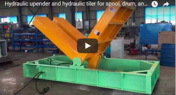
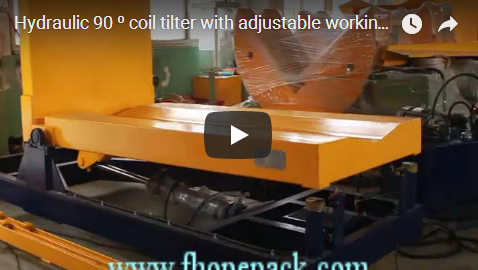
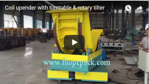
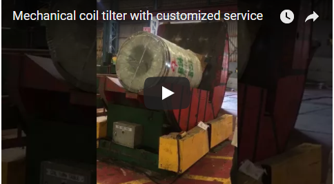
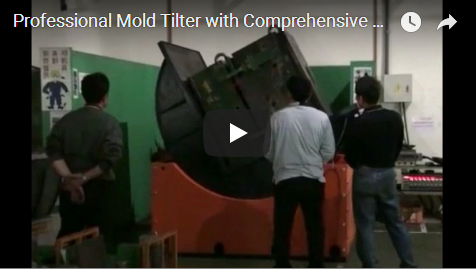
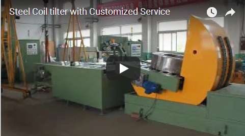
Kopsavilkums This customized transformer upender replaces high-risk crane maneuvers with a controlled 90-degree tilt. It is used in transformer assembly and maintenance inspection to protect the core and the operators. A reinforced mechanical chain drive or a synchronized gear-motor with VFD moves the load smoothly. Load ratings go to 10,000, 20,000, 50,000 and 100,000+ kg, and the platform is sized to your transformer per project.
Saturs
- What the transformer upender does
- Mechanical chain and motorized drive systems
- Load capacity and platform dimensions
- Hydraulic, mechanical and electrical safety systems
- PLC controls and factory integration
- Protecting cores, fins and casings
- Engineering and selection checklist
- Where an upender replaces crane handling
- Inženierijas bieži uzdotie jautājumi
- Nākamais solis
- Saistītā lasāmviela
- Avoti un standarti
What the transformer upender does
A transformer upender tilts a heavy power asset from horizontal to vertical, or back, on a dedicated platform instead of hanging it from a crane. The transformer stands on the platform, the machine rotates it through its tilt, and it arrives upright on the floor or on transport without jolts. That controlled movement is what protects the core windings and the operator in one step.
The machine serves two moments in the life of a transformer. In manufacturing, it positions the unit during assembly. In maintenance, it lays a heavy unit down or stands it up for inspection. Both cases need the same thing: stable, controlled rotation at whatever weight the transformer reaches.
Mechanical chain and motorized drive systems
The upender is offered with two drive configurations, and we choose by the weight and the duty of your unit.
The reinforced mechanical chain drive suits heavy-tonnage applications. Its chain links carry high torque with a large safety factor, and the drive keeps working through continuous industrial use.
The synchronized gear-motor system couples a gear motor to a variable frequency drive, or VFD. It gives a smooth soft start and soft stop, and that smoothness removes the jolts that can shift internal core windings on a delicate unit. Hydraulic models are also offered where the task calls for them, with anti-fall valves as part of the safety suite; the drive choice is confirmed per project.
For maintenance work on older transformers, the VFD is the preferred option. Its inching control moves the load a small angle at a time, so a technician watches the rotation at every degree instead of committing to one continuous motion.
Load capacity and platform dimensions
The machine is fully customizable to the extreme weights and dimensions of power transformers. The table below lists the standard heavy-duty series.
| Parametrs | Rūpnieciskais standarts |
|---|---|
| Maksimālā iekraušanas jauda | 10,000 / 20,000 / 50,000 / 100,000+ kg |
| Platform length (L) | 1,300–8,000 mm (pielāgojams) |
| Platform width (W) | 820–4,000 mm (pielāgojams) |
| Slīpuma leņķis | 90 ° |
| Rotācijas ātrums | 30 – 120 s (adjustable) |
| Jaudas jauda | 7.5 - 30.0 kW |
| Virsmas apdare | Anti-slip steel; PE or rubber protective padding per project for fins and sensitive casings |
| Standards and control interface | ISO 12100, EN ISO 13849-1, PLC signal |
The platform length and width are set to match the transformer base, so the unit sits inside the platform perimeter without lateral movement during the tilt. The rotation speed is adjusted to balance cycle time against the sensitivity of the load.
Hydraulic, mechanical and electrical safety systems
Safety is layered rather than single-point. Hydraulic models carry anti-fall valves that hold the load if pressure is lost. Every machine has a secondary mechanical lock that engages at rest, and limit switches that confirm the platform is in the safe position before any movement starts.
The controls are interlocked so the machine only operates when all safety perimeters are confirmed. That includes the platform being empty or loaded correctly, the working area being clear, and the mechanical lock being released at the right stage of the cycle.
PLC controls and factory integration
The control system is built around a PLC, and it can link by PLC signal to your factory management system. The upender then reports its stage and alarms into the line, and the maintenance planner sees completed tilts along with the other machines in the plant.
For a repeatable process, the same unit number recalls its tilt parameters, so a 10-tonne unit and a 50-tonne unit each run at their own speed and angle without an operator re-entering them. The linkage and the signal wiring are matched to your control architecture per project.
Protecting cores, fins and casings
A transformer is valuable because of what is inside, and the upender exists so nothing inside shifts. Options on the platform protect the outside as well. High-density PE or rubber buffers can be fitted to the platform surface, so delicate cooling fins and exterior casings do not get scratched or deformed during the tilt.
The structural frame is also built for eccentric loads. Transformers are rarely perfectly balanced on the platform, and the frame is designed to handle an offset center of gravity, keeping the machine from tipping over-center during the 45-degree transition phase of the tilt.
Engineering and selection checklist
Send us these points when you size an upender, and we confirm the configuration per project.
| Punkts | Ko mēs apstiprinām katrā projektā |
|---|---|
| Maksimālā iekraušanas jauda | kg, target the heaviest transformer you tilt |
| Platform length x width | mm, match the transformer base footprint |
| Rotācijas ātrums | s per tilt, balance cycle time and load sensitivity |
| Piedziņas veids | chain or gear-motor with VFD, by duty and weight |
| Enerģija | V / Hz / phase, match your site supply |
| Virsmas apdare | anti-slip steel or protective padding per unit |
| Safety and PLC interface | ISO 12100, EN ISO 13849-1, PLC signal per project |
Where an upender replaces crane handling
The upender fits operations that move large electrical assets: transformer manufacturing halls, repair plants and maintenance workshops, switchgear assembly, and any facility that lays a heavy unit down to reach its underside. In each of these, a crane can do the physical lift. Hanging a multi-tonne transformer from a hook and swinging it upright is where risk concentrates, the same reason 90-degree mold upenders are replacing crane flipping in toolrooms.
The upender takes that risk out of the hands of the crane operator. The load stays on a fixed platform, the tilt happens within the frame, and nobody stands under a suspended transformer. For sensitive non-ferrous coils, automated copper coil packaging lines from upending to stacking follow the same principle without surface damage.
Inženierijas bieži uzdotie jautājumi
Q: Why tilt a transformer with an upender instead of a crane? A: A crane swings the load through the air; the upender keeps it on a fixed platform. That protects the core windings and removes the risk of a suspended load.
Q: What load capacities are available? A: The standard series rates 10,000, 20,000, 50,000 and 100,000+ kg, and higher ratings are engineered per project.
Q: How long does a tilt take? A: Rotation speed is adjustable from 30 to 120 seconds per tilt, set per project by cycle time and load sensitivity.
Q: Do hydraulic models need an air supply? A: No. Air supply is not a standard utility requirement. Hydraulic models use dedicated hydraulic anti-fall valves, with site utilities confirmed per project.
Q: Can the machine link to our factory control system? A: Yes. The PLC sends stage and alarm signals to your management system, and the wiring is matched per project.
Q: What stops the load tipping during the tilt? A: The frame is designed for eccentric loads, and hydraulic anti-fall valves, a secondary mechanical lock and limit switches hold the platform through the transition.
Q: How do you size the platform? A: Platform length and width are set to the transformer base, so the unit stays inside the platform perimeter without lateral movement.
Nākamais solis
The upender is engineered from the unit you tilt, so the conversation starts with your transformers.
- Send the transformer weight, base dimensions and tilt frequency to info@fhopepack.com.
- We confirm the load rating, platform size and drive type for your operation.
- Mēs nodrošinām maketa rasējumu un objekta apsekojumu 48 stundu laikā.
- We quote the machine per project, including safety options and PLC linkage.
Pēdējoreiz pārskatīts: 2026-10-09
Saistītā lasāmviela
- Drošība pirmajā vietā ruļļu apstrādē: ražošanas grīdas risku samazināšana ar modernām ruļļu pacelšanas iekārtām
- Why Relying on Cranes for Steel Sheet Flipping is Costing Your Shop Money and Safety
- How 180-Degree Turning Machines Work for Precast Components and Sheets
- Palešu virpošanas mašīna un palešu invertors
- FHOPE galvenās vietnes produktu klāsts
Avoti un standarti
- ISO 12100:2010 — Mašīnu drošība: Vispārīgie projektēšanas principi
- EN ISO 13849-1:2023 — Ar drošību saistītās vadības sistēmu daļas: Funkcionālā drošība
- EN ISO 14120:2015 — Mašīnu aizsargi: Vispārīgās prasības
- EN 415-10:2014 — Iepakošanas mašīnu drošība: Vispārīgās prasības