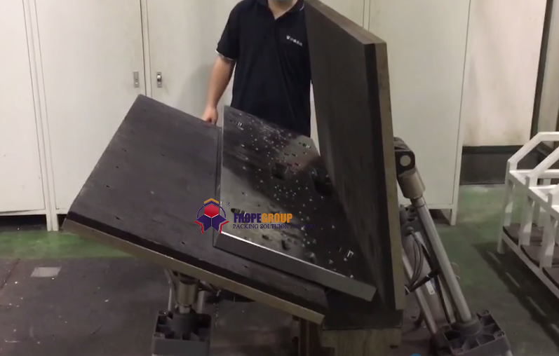
Effectus summary A roll-over cradle turns a heavy machine weldment without slings or a crane flip: the part sits in a curved rocker cradle, the cradle rolls on its curved base, and the part ends up on its side, turned through 90 degrees. Our equivalent solution turns heavy plates, weldments and castings the same way, sized to your heaviest part.
Table of Contents
- Quod machina facit
- Cur cunabula volubilia
- Radius et vestigium cunae
- Quod per partem statuimus
- Index selectionis
- salutem
- Quaestiones Frequentes de Ingeniaria
- tunc step
- Related reading
- sources
Quod machina facit
| Training | processus Description | Status Mechanicus |
|---|---|---|
| initium | A heavy weldment sits upright in a curved rocker cradle | The part is positioned against locating datum blocks; mechanical or hydraulic clamps secure the structural frame. |
| volvere | The cradle rolls smoothly along its curved base profile | Drive pinions, push cylinders, or gear segments initiate controlled rolling; the contact point shifts continuously along the foundation tracks. |
| Media conversio | The part leans over as the cradle advances | Center of gravity moves smoothly across the vertical plane without shock loading, sudden tipping, or cable rebound. |
| finis | The part rests flat on its side, fully turned through 90 degrees | The rocker reaches mechanical travel limit stops; positive locks engage before operators begin secondary machining or welding. |
| Shop integration | Pallets and incoming workpieces maintain clear staging zones | Surrounding workshop areas remain isolated from the active rolling corridor, keeping overhead crane lines clear for adjacent bays. |
Cur cunabula volubilia
- Conversio moderata. The part stays clamped securely inside the structural cradle during the entire rotational cycle. Dynamic shifting and uncontrolled tipping are eliminated.
- Nulla gruis conversio. The overhead crane is restricted purely to standard vertical loading and unloading. Riggers never perform dangerous free-air sling flips or side-pulling maneuvers.
- Onus pavimenti parvum. The circular rocker profile distributes the combined tare weight and payload across a moving linear contact zone, avoiding severe point-loading on concrete factory slabs.
- Quaelibet forma. Replaceable nest fixtures, adjustable V-blocks, and clamp tooling allow the cradle frame to accommodate irregular weldments, machine frames, and rough castings.
Alternative OEM Turning Solutions
For facilities handling distinct plate configurations or full inversion cycles, our engineering line includes complementary heavy-duty equipment:
- Hydraulic Plate Flippers: Engineered for heavy steel plates up to 12 metric tons (such as the FPFT series), utilizing high-pressure hydraulic cylinders to execute 90-degree vertical-to-horizontal reorientation on a fixed machine envelope.
- C-Frame Inverters: Designed for complete 180-degree rotation of bundled sheets, plates, or heavy structural assemblies up to 15 metric tons, featuring motorized drive systems and hydraulic clamping jaws.
Radius et vestigium cunae
A roll-over cradle rolling through 90 degrees travels along a linear path equal to a quarter of its pitch circumference.
Exemplum elaboratum (ad illustrandum):
| Parameter | Calculation / Definition | ratio |
|---|---|---|
| Cradle rocker radius (R) | Illustrative engineered radius | 1,500 mm |
| Quarter circumference travel | 3.14 × 2 × 1,500 mm ÷ 4 | LIII De mm |
| Cradle structural base length | Illustrative stationary frame footprint | 1,000 mm |
| Total floor length required | Travel distance + structural base length (2,360 mm + 1,000 mm) | LIII De mm |
Note: Clear safety margins must be maintained at both travel ends to satisfy operator clearance envelopes and perimeter guard fencing.
Quod per partem statuimus
Every turnover unit is engineered to match the dimensional envelope and weight distribution of your production components:
| Parametrus Machinae | Determinans Ingeniariae |
|---|---|
| Cradle radius and profile | Part outer boundary dimensions, swing clearance, and combined center of gravity (CoG) |
| Capacitas oneris structuralis | Heaviest weldment, casting, or raw plate assembly |
| Clamping fixtures and bolsters | Geometric contour, surface finish requirements, and datum clamp locations |
| Rotation angle range | Standard 90-degree tilt or expanded 180-degree roll-over configuration |
| Drive actuation system | Planetary gear roll drives, hydraulic rack systems, or cable-drum drives |
Index selectionis
Before finalizing machine sizing and foundation requirements, confirm the following technical parameters:
- Maximum and minimum part dimensions (Length × Width × Height).
- Maximum gross weight of the heaviest component.
- True center of gravity (CoG) coordinates in both raw and assembled states.
- Target rotation angle: 90 degrees or full 180 degrees.
- Total available workshop floor space, clear ceiling height, and crane approach vectors.
- Dedicated fixture interfaces required for non-rectangular weldments and castings.
- Target duty cycle and turns per work shift.
- Operator control preference: handheld push-button pendant, fixed console, or remote radio control.
salutem
Operating heavy roll-over machinery requires strict adherence to machinery safety standards:
- Perimeter protection: Establish a restricted exclusion zone along the entire dynamic travel path of the cradle using safety light curtains or interlocked perimeter fencing.
- Pre-rotation clamping verification: All mechanical hold-downs and hydraulic clamp locks must be engaged and confirmed via limit sensors before the roll cycle is permitted to start.
- Mechanical zero-lock: Before unlocking clamps or allowing personnel to inspect the turned workpiece, positive mechanical locking pins or brakes must secure the cradle in its end-stop position.
- Harmonized standards: For CE-conforming installations, equipment design and risk assessment comply directly with ISO 12100: 2010 (Safety of machinery — General principles for design) and relevant packaging/handling safety provisions of LAT-415 10: 2014.
Quaestiones Frequentes de Ingeniaria
Q: What does a roll-over cradle do? A: It reorients heavy structural weldments, machine frames, castings, or plates by rolling along a precision curved rocker base, eliminating dangerous crane-sling flipping.
Q: How much floor space does it need? A: For a 90-degree turn, the linear floor travel equals roughly one-quarter of the rocker’s circumference plus the physical length of the machine base. In our 1,500 mm radius example, this equals approximately 3,360 mm of linear space.
Q: Can it turn 180 degrees? A: Yes. A 180-degree turn requires an extended semi-circular rocker base, appropriate drive mechanisms, and a longer floor roll path. Alternatively, C-frame mechanical inverters can achieve 180-degree turns within a fixed stationary envelope.
Q: Is it only suitable for flat plates? A: No. While it efficiently flips heavy plates, it is widely utilized for complex three-dimensional weldments and asymmetric castings through custom-machined nesting blocks and adjustable clamps.
Q: Can you build custom roll-over cradles? A: Yes. We manufacture custom-engineered roll-over cradles, hydraulic flippers, and mechanical upenders designed around your heaviest workpiece envelope and specific shop layouts.
Q: Which international standards apply to this machine? A: For CE installations, our turnover machines are designed and manufactured in accordance with ISO 12100:2010 for mechanical safety and EN 415-10:2014 for integration safety.
tunc step
We match the correct roll-over cradle or turnover machine to your production line in three steps:
- Delineationem tuam submitte and component specifications (dimensions, maximum weight, center of gravity) to info@fhopepack.com.
- Propositionem technicam formalem intra horas XLVIII accipe., complete with general arrangement layout drawings, load ratings, and cycle times.
- Book a site survey or virtual review with our application engineers to confirm floor loading capacity and clear installation clearances.
Related reading
- Volubilis Laminae Ferreae Loco Volubilis Gruis
- Invertens cum Fixatura Speciali pro Fusionibus Gravibus
- Magnae Formae Volutae ad 180 Gradus Vertendum
- Machina ad laminas ferreas vertendas et invertendas
sources
- Data technica machinae: turma machinatorum FHOPE, 2026-10-10
- Cradle kinematic geometry and footprint model: illustrative worked engineering example
- Standards reference: ISO 12100:2010 (Safety of machinery); LAT-415 10: 2014 (Packaging and handling safety)
- Technical response protocol: standard engineering quotation SLA (proposal within 48 hours)
Ultima recensio: 2026-10-29