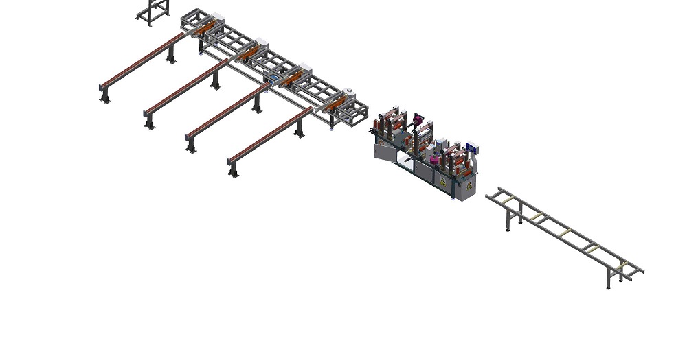
Ringkasan Eksekutif — A horizontal door and panel wrapping machine automates the protective packaging of single flat panels, pre-hung doors, and architectural slabs directly along a powered roller conveyor datum. Designed as an inline alternative to manual film taping and high-energy thermal shrink tunnels, this cold-wrapping system utilizes a dynamic orbital ring to apply pre-tensioned stretch film across top faces, bottom undersides, and longitudinal edges (typically 20–35 µm LLDPE film at 150%–250% motorized pre-stretch). By maintaining workpieces completely flat throughout the cycle, it eliminates part tipping, surface scratching, and thermal distortion risks for high-value joinery, lacquered doors, and insulated composite panels.
1. Machine Kinematics & Sequential Line Execution
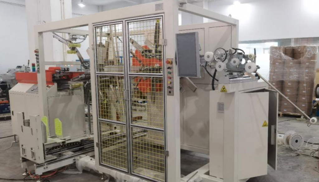
A dedicated horizontal door and panel wrapping machine automates protective packaging by conveying flat building components continuously through an enclosed orbital ring:
[Infeed Powered Conveyor] ──> [Optical Sizing & Centering] ──> [Pneumatic Top Press Rollers] ──> [Orbital Ring Wrap] ──> [Pneumatic Cut & Wipe] ──> [Outfeed Staging]
Urutan Pemrosesan Langkah demi Langkah
| Tahap Urutan | Aksi Mekanis | Engineering Control Mechanism |
|---|---|---|
| 1. Infeed Positioning | The panel advances linearly along vulcanized PU-sleeved powered rollers. | Infeed through-beam optical sensors register the leading edge, initiating motorized side-centering guides. |
| 2. Clamping & Initiation | Overhead press rollers descend to clamp the load; the ring accelerates from zero datum. | Proportional pneumatic regulation (0.15–0.30 MPa) suppresses board chatter; soft-start VFD prevents film snap. |
| 3. Continuous Helical Wrap | The carriage orbits continuously around the passing panel, depositing overlapping film. | Independent inverter drives synchronize conveyor linear speed with ring RPM to maintain constant film pitch. |
| 4. Cut, Wipe & Outfeed | Pneumatic scissor jaws grip the web, a hot-wire or serrated blade cuts, and a soft brush wipes the tail flat. | The wrapped panel discharges smoothly onto downstream gravity or driven accumulation beds. |
Because workpieces remain completely horizontal from infeed to discharge, the line eliminates vertical reorientation, tipping risks, and structural deflection on heavy solid core or pre-glazed fire doors.
2. Target Production Settings: Where Single-Piece Wrapping Fits
Applying an automated single-piece stretch wrap serves as the final surface preservation milestone prior to internal staging, vertical carting, or direct logistics dispatch:
| Kategori Aplikasi | Tujuan Perlindungan Utama | Target Production Setting |
|---|---|---|
| Finished Solid & Hollow Doors | Protects high-gloss lacquer, painted faces, natural wood veneers, and rebated edge profiles. | Automated door manufacturing plants, high-mix architectural joinery shops. |
| Assembled Window & Door Frames | Secures integrated glazing, weatherstripping seals, and extruded aluminum or uPVC frames. | Pre-hung assembly plants, commercial facade and window fabrication bays. |
| Engineered Boards & Panels | Shields raw particleboard edges, decorative melamine skins, and acoustic perforations. | High-capacity MDF, OSB, and architectural sandwich panel processing lines. |
3. Technology Comparison: Cold Stretch Wrapping vs. Thermal Shrink Tunnels
When evaluating secondary packaging methods for finished panels, packaging engineers balance thermal risks, power budgets, and mechanical footprints:
| Variabel Teknis | Cold Orbital Stretch Wrapping (FHOPE) | Thermal Shrink Tunnel Systems |
|---|---|---|
| Connected Power Demand | 4.5 kW - 7.5 kW (Inverter motors only) | 30.0 kW - 60.0 kW (Continuous heating banks) |
| Thermal Distortion Risk | Zero thermal stress; ambient cold application | High risk of veneer blistering, adhesive melt, and hollow core warping |
| Edge Stress Profile | Elastic recovery exerts balanced hoop tension | Inward cooling shrinkage crushes fragile decorative moldings and stepped rabbets |
| Machine Floor Footprint | Compact (typically 4.0 m – 6.0 m total length) | Extended footprint (8.0 m – 12.0 m for heat chamber and cool-down zones) |
| Pelestarian Permukaan Akhir | Smooth cast LLDPE conforms cleanly without sticking | Molten shrink film can adhere to un-cured lacquers or warm paint coatings |
4. Geometric Ring Sizing: The High Aspect-Ratio Envelope
Standard architectural doors present extreme aspect ratios (e.g., 900 mm wide × 45 mm thick). Equipment sizing must be governed by the true operational diagonal envelope, factoring in the radial space occupied by the rotating film carriage and pneumatic hold-down hardware:
   +-----------------------------------------------+
   |             Orbital Ring Steel ID             |
   |                                               |
   |         +---------------------------+         |
   |         | Carriage & Film Roll Clear|         |
   |         |   (H_carriage + C_safety) |         |
   |         +---------------------------+         |
   |                                               |
   |         +---------------------------+         |
   |         |   Door / Panel Profile    | T       |
   |         +---------------------------+         |
   |                       W                       |
   +-----------------------------------------------+
True Ring Bore Minimum Diameter Formulation
D_ring_inner ≥ √(Width² + Thickness²) + 2 × (H_carriage + C_safety)
Dimana:
- Width = Maximum door or panel width across the roller bed (mm)
- Thickness = Maximum panel thickness including projecting moldings or handles (mm)
- H_carriage = Radial depth of the film carriage + full film roll OD (standard: 130–160 mm)
- C_safety = Dynamic operating clearance (minimum 50 mm recommended to absorb tracking skew)
Verification Scenarios
-
Scenario A: Standard Interior Door (900 mm W × 45 mm T): Diagonal = √(900² + 45²) = √(810000 + 2025) ≈ 901.1 mm Minimum Ring ID = 901.1 + 2 × (140 + 50) = 1281.1 mm Recommendation: Select the FHOPE E1400 Series (1,400 mm clear ring bore).
-
Scenario B: Commercial Double-Leaf / Facade Panel (1,200 mm W × 80 mm T): Diagonal = √(1200² + 80²) = √(1440000 + 6400) ≈ 1202.7 mm Minimum Ring ID = 1202.7 + 2 × (140 + 50) = 1582.7 mm Recommendation: Select the FHOPE E1600 / E1800 Series.
5. Kinematic Synchronization: Speed, Pitch, and Film Overlap
Spiral overlap percentage determines containment force and edge barrier performance:
Linear Pitch per Turn (P) = [Conveyor Velocity (m/min) × 1000] / Ring Velocity (RPM) [mm/rev] Effective Overlap Ratio = [1 – (P / W_effective)] × 100%
Where W_effective represents nominal film width minus transverse neck-in under tension: W_effective ≈ W_nominal × 0.85
Speed & Overlap Benchmark Table (250 mm Film Width, Effective Width = 212 mm)
| Conveyor Speed (V_c) | Ring Speed (ω_ring) | Linear Pitch (P) | Resulting Film Overlap | Application Grade & Consumption |
|---|---|---|---|---|
| 5.0 m / mnt | 50 RPM | 100 mm | Tumpang tindih ~53% | Standard production default; double-layer continuous dust/scratch seal |
| 7.5 m / mnt | 50 RPM | 150 mm | Tumpang tindih ~29% | High-speed economic wrap for internal warehouse transfer |
| 3.5 m / mnt | 60 RPM | 58 mm | Tumpang tindih ~73% | Heavy export grade; enhanced edge cushioning for long-haul flatbed freight |
6. Technical Specifications Matrix: Standard vs. Heavy-Duty Panel Wrappers
| Parameter Desain | Standard Door Cell (E1400) | Heavy Architectural Cell (E2000) | Sizing & Compliance Impact |
|---|---|---|---|
| Lebar Panel Maksimum | Hingga mm 1,200 | Hingga mm 1,800 | Dictates roller conveyor width and ring bore |
| Max Panel Thickness | 100 mm | 150 mm (Custom up to 300 mm) | Sized to clear overhead hold-down stroke |
| Panjang Panel Minimum | 1,000 mm (Shorter with bridge rollers) | 1,200 mm | Governed by infeed/outfeed transfer roller pitch |
| Payload Rating | 20 – 120 kg per unit | Up to 350 kg per panel | Sized for solid fire doors or precast slabs |
| Kecepatan Linier Konveyor | 5 – 15 m/min (Inverter duty) | 3 – 12 m/min (Inverter duty) | Synchronized via central PLC encoder bus |
| Kecepatan Cincin Orbital | 10 – 60 RPM (Dynamic braking) | 10 – 45 RPM (Heavy slewing drive) | Inverter S-curve soft acceleration |
| Pra-Peregangan Bertenaga | 150% – 250% fixed-gear ratio | 150% – 300% variable dual-motor | Minimizes film tension on delicate door corners |
| Roller Sheathing | Vulcanized Polyurethane (Shore A 75) | Heavy-duty NBR / Vulcanized PU | Non-marking contact to prevent paint marring |
| Persyaratan Pneumatik | 0.5 – 0.7 MPa (Clean, dry air) | 0.6 – 0.8 MPa (Clean, dry air) | Regulates top hold-downs and cutting jaws |
| Connected Power Rating | ~4.5 kW, 3-Phase 380V/480V | ~7.5 kW, 3-Phase 380V/480V | Low electrical consumption footprint |
7. Functional Safety Systems & Machinery Directives
Safe high-speed packaging requires compliance with international machinery safety standards:
[ 2,000 mm Physical Wire-Mesh Perimeter (EN ISO 14120) ] │ [ Infeed/Outfeed Category 4 Optical Safety Light Curtains (EN ISO 13849-1) ] │ [ Interlocked Maintenance Doors with Category 3 / PL d Safety Switches ] │ [ Automatic Residual Pneumatic Exhaust Dump Valves (OSHA 1910.147 LOTO) ]
- Machinery Safety Directives: Full conformity with EN ISO 12100:2010 (Risk assessment and risk reduction principles) and packaging machine standards under EN 415-10:2014.
- Electrical Safety Protocols: Built to EN 60204-1:2018, providing IP54 control cabinets, low-voltage 24V DC control circuits, and continuous equipment grounding.
- Pneumatic Zero-Energy State: Emergency stop actuation immediately trips pneumatic exhaust dump valves, removing residual pressure from vertical hold-down cylinders to eliminate pinch hazards during manual clearing.
8. Daftar Periksa Seleksi Teknik
Verify the following production parameters prior to final layout drafting:
- Workpiece Sizing Matrix: Minimum and maximum panel length, width, and thickness (including projecting handles or trims).
- Unit Weight Spectrum: Net weight of the lightest hollow-core door and heaviest solid architectural slab.
- Finished Surface Sensitivity: Primer-coated, high-gloss polyurethane lacquer, raw wood veneer, or anodized aluminum.
- Throughput Demand: Required production output in finished panels per hour.
- Packaging Material Specification: Cast LLDPE stretch film (20–35 µm) and spool core diameter (typically 76 mm).
- Conveyor Pass-Line Elevation: Exact factory datum height (standard: 800 mm ± 50 mm) to align with upstream saws or sanders.
- Automation Architecture: Standalone operator cell or inline integration via industrial Ethernet (PROFINET / EtherNet-IP).
9. Engineering Frequently Asked Questions
Q: Can cold stretch wrapping damage delicate painted or high-gloss surfaces? A: No. Conveyor rollers are sleeved in non-marking Shore A 75 polyurethane or NBR rubber, completely eliminating metal-to-metal rubbing. Furthermore, the powered pre-stretch carriage elongates the film before it leaves the dispenser, meaning the film touches the panel with uniform elastic recovery rather than abrasive sliding friction.
Q: How does the system handle wide, thin panels without lifting them off the rollers? A: Thin panels with broad surface areas are susceptible to aerodynamic flutter and tangential film pulling. The machine utilizes synchronized overhead pneumatic press rollers lined with non-marking soft rubber. Regulated under low pressure (0.15–0.25 MPa), these rollers exert stabilizing downforce along the workpiece centerline, keeping the board seated firmly on the drive rollers.
Q: Does the system require a human operator during wrapping? A: No. Infeed optical sensors register panel presence, overhead clamps engage dynamically, the film carriage anchors and wraps the part, and the pneumatic cutter and brush finish the tail automatically. Personnel are required only for loading raw film rolls and routine maintenance.
Q: What is the maximum throughput achievable on standard interior doors? A: For a standard 2,000 mm door running at a conveyor speed of 6.0 m/min with 50% overlap, active wrapping requires approximately 20 seconds. Factoring in infeed positioning and tail cutting, total floor-to-floor cycle time runs between 28 and 35 seconds per door (yielding 90 to 110 doors per hour).
10. Langkah Selanjutnya: Rekayasa Tata Letak & Proposal
- Submit Panel Sizing Matrix: Forward your minimum and maximum panel dimensions (L × W × H), maximum unit weight, and required hourly throughput to info@fhopepack.com.
- Receive 2D/3D CAD Layout: Our engineering group provides a certified 2D General Arrangement (GA) layout drawing, dynamic clearance simulation, and station cycle time breakdown within 48 hours.
- Factory Acceptance Testing (FAT): Ship sample finished doors or composite boards to FHOPE’s testing facility to verify zero-scratch clamping, calibrate film overlap, and confirm line handshakes prior to equipment dispatch.
Standar & Referensi Teknis
- EN 415-10:2014: Safety of packaging machines — Part 10: General requirements for horizontal orbital wrapping systems.
- EN ISO 12100:2010: Safety of machinery — General principles for design — Risk assessment and risk reduction.
- EN ISO 13849-1: Safety of machinery — Safety-related parts of control systems.
- EN 60204-1:2018: Safety of machinery — Electrical equipment of machines — Part 1: General requirements.
- ASTM D4649-03(2016): Standard Guide for Selection and Use of Stretch Wrap Films.
- FHOPE Engineering Standards: E-Series Horizontal Orbital Door & Panel Wrapping Systems FAT Protocol (Revision 2026).