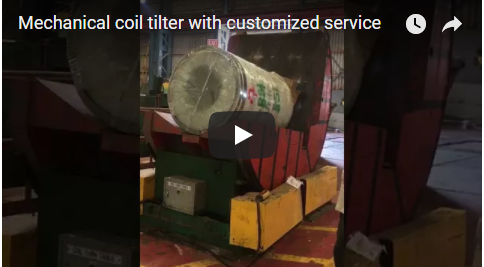
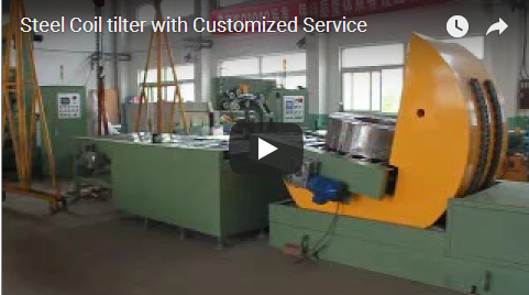
Préface A mechanical coil tilter with a sliding table rotates heavy coils and palletized loads through 90°, transitioning loads between eye-to-sky (vertical axis) and eye-to-horizon (horizontal axis) attitudes. Integrating a powered rail-guided sliding table allows the load platform to travel horizontally clear of the main C-frame structure, providing unobstructed vertical clearance for overhead crane hooks and C-hooks, or roll-in access for forklifts. Sized for coils up to OD 1400 mm and 1200 mm in width, the heavy-duty 5 T upender operates via a variable-frequency drive (VFD) for controlled single-way or two-way tilt-and-return sequences.
Table des Matières
- Ce que fait la machine, dans l'ordre
- Que fait un basculeur de bobines à table coulissante ?
- Turn and return cycle time
- Spécifications techniques
- Contrôle du takt
- Liste de contrôle de sélection
- Commandes et sécurité
- QFP
- Suivant
- Related reading and sources
Ce que fait la machine, dans l'ordre
The mechanical upender executes its tilting sequence through synchronized mechanical drive linkages and electromechanical safety interlocks:
- Load Placement on Extended Table: The sliding table moves out along hardened ground guide rails away from the C-frame. The overhead crane or forklift lowers the film-wrapped coil onto the 1400 × 1200 mm table surface without risk of rigging hitting the upper frame.
- Table Retraction to Home Position: The driven sliding table traverses backward into the structural throat of the heavy-duty C-frame and locks into the tilt cradle via mechanical stops and proximity limit switches.
- 90-Degree Upending Motion: Driven by a motor with variable-frequency speed regulation, the C-frame turns about its main pivot shaft. The internal face and base support both sides of the coil continuously, holding the load firmly without relative slip to protect packaging film and strip edges.
- 90-Degree Final Attitude Dwell: The load reaches its horizontal attitude on its side, ready for extraction or further handling.
- Return Cycle or Direct Discharge: In a two-way operational layout, the frame tilts back 90° to the upright position once the workpiece is transferred. In a one-way layout, the load is discharged directly in the new attitude before the bare cradle returns.
Que fait un basculeur de bobines à table coulissante ?
A standard mechanical upender reorients coils between palletized eye-to-sky storage orientation and horizontal uncoiler mandrels. However, static frames often restrict overhead crane maneuvering because the top arm of the cradle obstructs direct vertical drops.
The rail-guided sliding table resolves this material handling conflict:
- Liquidation: the table shuttles horizontally outside the machine footprint, so slings, crane ropes and forklift masts reach the load without obstruction.
- Surface and Edge Integrity: Because the cradle supports the load on two orthogonal faces throughout the 90° sweep, the coil never slides across surfaces. Packaging integrity, stretch wrap, and edge conditions remain intact.
- Protection du disque: The table drive and main tilt drive feature electrical interlocking, ensuring that the C-frame cannot tilt while the sliding table is in motion or extended, and the table cannot travel unless the tilt cradle is fully horizontal at 0°.
| Sous-système de machine | Engineering Sizing Basis |
|---|---|
| Ouverture en C | Load outer diameter (OD up to 1400 mm) and coil width (up to 1200 mm) |
| Sliding table and track | Total footprint, structural travel stroke, and loading method |
| Pivot shaft and gear drive | Dynamic overturning moment at 5 T rated capacity |
| Integrated lifting lugs | Rigging calculations for factory installation and bay relocation |
Turn and return cycle time
Cycle timing depends on the drive profile programmed into the independent variable-frequency drive (VFD) control cabinet. Under typical factory commissioning parameters:
| Motion Step | Durée illustrative | Fonction d'ingénierie |
|---|---|---|
| Dwell / Infeed verification | ~ 12 s | Signal handshaking, clamping confirmation, and brake release |
| 90° Upending turn | ~ 24 s | Controlled acceleration, deceleration, and smooth load reorientation |
| 90° Reverse return | ~ 12 s | Unloaded or counterbalanced return to home position at higher frequency |
| Total dynamic tilt cycle | ~ 36 s | Motion window excluding horizontal table transit and crane rigging |
The forward rotation is configured slower than the return stroke to minimize dynamic inertia and prevent load shift as the center of gravity crosses the tilt axis. In single-way operations, the coil departs directly in its reoriented attitude; in two-way setups, the frame returns to accept the next incoming piece.
Spécifications techniques
Our 5 T sliding-table upender is built for industrial coil staging. Below are the verified machine specifications alongside standard production models in the mechanical tilter portfolio:
5 T Sliding-Table Model Specifications
| Paramètre | Valeur |
|---|---|
| Capacité nominale | 5 T |
| Diamètre extérieur maximal de la bobine | 1400 mm |
| Largeur de bobine maximale | 1200 mm |
| Table platform | 1400 x 1200 mm |
| Turn-over angle | 90°, single-way or two-way |
| Encombrement | Approx. L3000 × W2200 × H2600 mm, excluding rail runout |
| Poids de la machine | Environ 4 T |
| alimentation électrique | CA 380 V, 60 Hz |
| Contrôle | Independent cabinet with VFD speed control |
| Voyage de table | Motorized sliding platform for crane and forklift clearance |
Model Cross-Reference: Standard FPCT Series
The mechanical tilter line spans 12 configurations; the FPCT duty ratings are:
| Série de modèles | Charge maxi | Puissance motrice | Vitesse de fonctionnement typique | Tension |
|---|---|---|---|---|
| FPCT-03 | 3 T | 1.3kW | 50–90 s / cycle | 380 V CA, 50 Hz (personnalisable) |
| FPCT-05 | 5 T | 2.0kW | 50–90 s / cycle | 380 V CA, 50 Hz (personnalisable) |
| FPCT-10 | 10 T | 4.5kW | 60–90 s / cycle | 380 V CA, 50 Hz (personnalisable) |
Custom frames cover wire coils, master steel coils, copper coils, moulds and sheet bundles.
Contrôle du takt
Balance dynamic motion against handling time to confirm throughput.
- Target takt: 30 coils per hour, so 3600 s ÷ 30 = 120 s per coil.
- C-frame motion: about 36 s (24 s turn plus 12 s return).
- Handling budget left: 120 s − 36 s = 84 s.
Inside that 84 s the plant must run the table out (about 15–20 s), engage and place the crane hook (about 30–40 s), and bring the table home with interlock confirmation (about 15–20 s). Those figures are illustrative and should be timed on your own floor; when they fit inside 84 s, one 5 T sliding-table upender covers 30 coils per hour.
Liste de contrôle de sélection
- Charge: coil OD up to 1400 mm, width up to 1200 mm, weight up to 5 T.
- Attitude: do coils arrive eye-to-sky on a pallet or eye-to-horizon on saddles?
- Mouvement: single-way turnover for continuous exit, or two-way tilt-and-return.
- Chargement: crane hook, C-hook, forklift prongs or ground conveyor.
- Rail stroke: set from building crane clearance and the safety zone.
- Empreinte: L3000 × W2200 × H2600 mm plus the sliding travel.
- Approvisionnement: AC 380 V 60 Hz three-phase, or your plant voltage.
Commandes et sécurité
Tilting heavy dynamic loads needs structural and electromechanical precautions:
- Motion envelope: the C-frame swing and the table path are the danger zones. Safeguarding is selected from the site risk assessment: fixed guards at the pivot and rails, interlocked access where operators load, and E-stops at the control station.
- Drive interlocking: the frame cannot rotate until the table confirms home position on redundant limit switches.
- Load retention: a motor brake or holding valve stops cradle movement if power is lost, and no load is left tilted during maintenance unless it is mechanically blocked.
- Normes: design follows ISO 12100:2010 and the EN 415-10 packaging-machinery framework, with LOTO procedure for electrical work.
QFP
Why incorporate a sliding table instead of a standard fixed upender? The motorized sliding table carries the coil outward from under the overhead frame structure. This removes physical overhead obstructions, permitting industrial cranes and C-hooks to lower coils directly without collision risks.
What are its dimensions and capacity? 5 T maximum load, coil OD to 1400 mm and width to 1200 mm on a 1400 × 1200 mm table, inside a footprint of about L3000 × W2200 × H2600 mm.
What is the complete operational cycle time? The rotational sweep takes approximately 36 s (24 s turn plus 12 s return). Total line cycle time is determined by adding horizontal table travel and crane handling intervals.
Suivant
- Send coil and facility data: maximum OD, width, weight, crane hook clearance and target takt to info@fhopepack.com.
- Get the layout: equipment drawing, footprint plot and cycle-time calculation within 24 to 48 hours.
- Check foundations: confirm anchoring, utility hookups and barrier positions with our engineers.
Related reading and sources
- Redresseur et basculeur avec table coulissante
- Coil tilter and upender FPCT series
- Mechanical tilter product range
Engineering Standards & References
- ISO 12100:2010 – Sécurité des machines — Principes généraux de conception — Évaluation et réduction des risques.
- EN 415-10:2014 – Sécurité des machines d'emballage — Partie 10 : Exigences générales.
Dernière mise à jour : 05/11/2026