> **Shrnutí**
>
> A steel sheet flipper turns heavy plate between faces so the next process can work the other side without crane gymnastics. Our hydraulic FPFT-12 takes up to 12 t, with platform size 4,600 × 2,500 × 1,400 mm and dual 500 × 1,800 mm working tables. A worked example checks an 8 t plate stack against that load and estimates cycle time with forklift loading.
Obsah
- Why sheets need a dedicated flipper
- Layout: dual tables and hydraulic drive
- Zobrazený stroj
- FPFT-12 sheet flipper data
- Worked example: an 8 t plate stack
- Kontrolní seznam pro výběr: co nám poslat
- Bezpečnost a EN 415-10
- Často kladené otázky k inženýrství
- Další krok
- Související čtení
- Zdroje
Why sheets need a dedicated flipper
Turning a multi-ton plate stack with a crane alone risks edge damage and uncontrolled swing. A hydraulic sheet flipper keeps the stack on a fixed path between two tables, so operators stay clear of the load and the next process sees a square, undamaged face.
Typical plate size on our FPFT page is thickness 50–300 mm and plan size about 1,800 × 2,500–2,800 mm at up to 12 t. Thinner sheet packs and thicker blocks are sized on the order drawing.
Layout: dual tables and hydraulic drive
FPFT-12 uses two working tables (A and B). Each table contact face is listed as 500 × 1,800 mm; that is the platen arm bearing face, and wider stacks overhang within the stated plate plan range.
The product loads onto one table by forklift, crane or hoist. Hydraulics turn the loaded table toward the upright receive position on the second table, then complete the hand-off so the stack rests on its other face. Turning speed is adjustable. Double-acting cylinders drive the motion; max system pressure is 15 MPa (allowance 20 MPa).
The machine can stop at an intermediate angle with pressure holding. Mechanical and electric stop blocks limit the stroke. Control is from a pedestal panel or remote. Soft covers shield the working area.
Zobrazený stroj
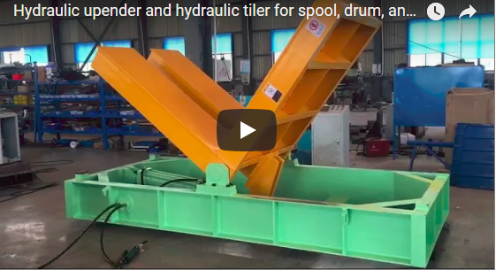
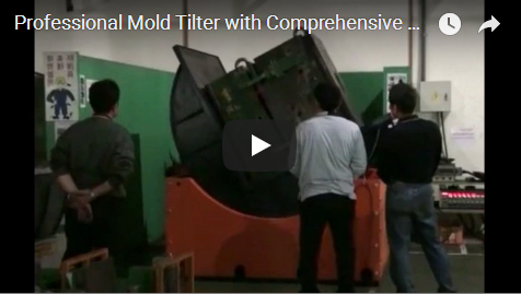
Our dark-grey hydraulic sheet flipper runs an empty platform through a full flip: the upper platen rises from a tilt, passes vertical and settles on the opposite face. Parallel metal bars form the load face. A side-mounted control panel with buttons and red/green indicators sits on the machine body. No workpiece is loaded in this demo cycle.
FPFT-12 sheet flipper data
| Item | FPFT-12 |
| :--- | :--- |
| Platform (L × W × H) | 4,600 × 2,500 × 1,400 mm |
| Max flipping load | 12 t |
| Motor output | 8.0 kW |
| Working tables | A/B each 500 × 1,800 mm |
| Max pressure | 15 MPa (allowance 20 MPa) |
| Power supply | 380 V 3P 50 Hz |
| Loading | Forklift / crane / hoist |
| Typical plate | thickness 50–300 mm; plan about 1,800 × 2,500–2,800 mm |
Machine mass and oil volume on the product page are listed for the built unit; confirm them on the order drawing for your options package. Drive type on this page is hydraulic (not the mechanical coil upender gear-motor family).
Worked example: an 8 t plate stack
Illustrative stack: 2,400 × 1,800 mm plan, total mass 8 t, forklift loading, target flip between faces for grinding the second side.
**Load check.** 8 t < 12 t FPFT-12 limit → class OK. Plan 2,400 × 1,800 mm sits inside the stated plate range around 1,800 × 2,500–2,800 mm; confirm bar spacing on the platen matches the stack footprint. **Cycle sketch.** Forklift sets the stack on table A (~60–90 s). Hydraulic flip and hand-off to table B is typically under two minutes once speed is set for the load. Forklift removes the flipped stack (~60–90 s). Gross station time is often about 4–6 minutes per stack when forklift is the bottleneck; send your real forklift takt if you need a line balance. **Takeaway.** Load headroom is 4 t on this example. Send thickness, plan size and max stack weight before we freeze the FPFT class.
Kontrolní seznam pro výběr: co nám poslat
1. Plate or stack plan size, thickness and max weight.
2. Flip angle required (180° total inversion via dual 90° transfer cradles vs single 90° upending).
3. Loading method: forklift, crane or hoist.
4. Duty: stacks per hour and shift length.
5. Destination market for the safety file.
Bezpečnost a EN 415-10
For CE markets we use EN 415-10 as the packaging / handling-machine reference, with a risk assessment to ISO 12100. The main hazards are the moving platen, pinch at the tables and the load interface. Soft covers, mechanical/electric stop blocks, position lock on power loss and a clear operator stance at the pedestal are part of the standard layout. Perimeter rules for the forklift path are set in the project risk file.
Často kladené otázky k inženýrství
Q: Is FPFT the same as a mold upender (FPMT)?
A: No. FPFT here is the hydraulic steel sheet flipper family on the sheet-flipper product page. Mold upenders are a different series; do not mix their page numbers.
Q: Can it stop mid-cycle?
A: Yes. The machine can stop at an intermediate angle with hydraulic pressure holding, and it has automatic position lock on accidental power-off.
Q: Mechanical or hydraulic drive?
A: This page’s FPFT-12 is hydraulic with double-acting cylinders. Mechanical gear-motor upenders are a separate family for coils.
Q: Which standard do you cite for CE?
A: EN 415-10 with an ISO 12100 risk assessment.
Další krok
1. **Send plate size, thickness and max stack weight** to info@fhopepack.com.
2. **We map it** to FPFT-12 or a neighbouring class and note table options.
3. **We reply within 24 hours** with a layout sketch and a cycle estimate.
Související čtení
- [Steel Sheet 180 Degree Turning and Upending Process](https://www.fhopepack.com/videos/steel-sheet-180-degree-turning-and-upending-process/)
- [Steel Sheet Upender for 180 Degree Safety Turning](https://www.fhopepack.com/videos/steel-sheet-upender-for-180-degree-safety-turning/)
- [Steel Plate Strapping Machine](https://www.fhopepack.com/videos/steel-plate-strapping-machine/)
- [Packaging Equipment: Technology and Best Practices](https://www.fhopepack.com/videos/steel-sheet-and-frame-flipping-turning-machine/)
- [Steel Sheet Flipper and Upender machine (product)](https://www.fhopepack.com/Hydraulic/Steel-Sheet-Flipper-and-Upender-machine.html)
Zdroje
- FHOPE Hydraulic Steel Sheet Flipper and Upender machine product page: FPFT-12 data (load, dimensions, tables, pressure, power)
- Machine features from our sheet flipper demo (dark-grey body, parallel-bar platen, side panel)
- Worked example: illustrative stack figures
- Normy: EN 415-10; ISO 12100:2010
Naposledy zkontrolováno: 18. 10. 2026