> **Executive summary**
>
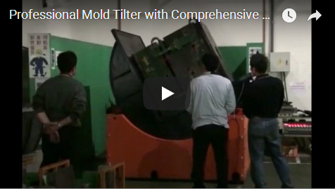
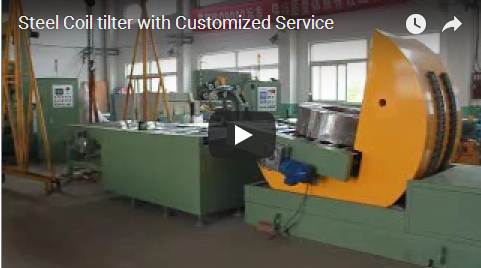
> Coil upending rotates a heavy coil through 90° between eye-horizontal (bore-horizontal) and eye-vertical (bore-vertical, or eye-to-sky) orientations. This mechanical transition is essential for palletizing, decoiler mandrel loading, slit-coil strapping, and export container packaging. A dedicated 180° flipper turnover unit inverts dies, molds, and double-sided assemblies entirely. Our FPCT mechanical upenders handle heavy coil payloads from 3 t to 20 t within stable 50–100 s operating cycles on a fixed heavy-duty pivot. The operator controls the process safely from outside the perimeter interlocked fence. Below is the complete engineering guide covering machine kinematics, technical ratings, an 8 t sizing model, and safety compliance.
<iframe loading="lazy" width="940" height="535" src="https://www.youtube.com/embed/neTi6OPdfS0?rel=0" frameborder="0" allow="accelerometer; autoplay; clipboard-write; encrypted-media; gyroscope; picture-in-picture; web-share" allowfullscreen></iframe>

---

<h2 id="table-of-contents">Table of Contents</h2>

<ul>
<li><a href="#why">Why industry upends and turns coils</a></li>
<li><a href="#types">Upending and turning solutions</a></li>
<li><a href="#how">How a mechanical upender works</a></li>
<li><a href="#specs">FPCT upender data</a></li>
<li><a href="#example">Sizing example: an 8 t coil</a></li>
<li><a href="#selection-checklist">Selection checklist</a></li>
<li><a href="#safety">Safety: EN 415-10 and ISO 12100</a></li>
<li><a href="#engineering-faq">Engineering FAQ</a></li>
<li><a href="#next-step">Next step</a></li>
<li><a href="#related-reading">Related reading</a></li>
<li><a href="#sources">Sources</a></li>
</ul>

<h2 id="why">Why industry upends and turns coils</h2>

Steel, aluminum, copper, and wire coils change orientations multiple times across slitting, annealing, staging, and final packaging:

- **Slitting lines and rolling mills** discharge slit coils horizontally on a mandrel or exit turnstile (eye-horizontal).
- **Automated warehouse storage, wooden shipping pallets, and uncoilers** require coils rested flat on their face (eye-vertical / eye-to-sky) to prevent roll-away hazards and perimeter bore sag.
- **Export wrapping lines** often require the batch to be upended back to eye-horizontal for circumferential through-the-eye orbital wrapping.

Executing this 90° transition with an overhead crane hook, wire ropes, or C-hooks introduces severe industrial hazards. Suspended coils swing unpredictably through the air, rigging chains bite into and damage strip edges, and personnel face catastrophic crush exposure.

A mechanical coil upender eliminates crane-assisted tilting. The coil rests securely inside an engineered, reinforced cradle. The operator remains at a remote pedestal outside the safety zone, executing smooth, repeatable 90° reorientation cycles.

<h2 id="types">Upending and turning solutions</h2>

Industrial tilting demands vary by load geometry, center of gravity (CoG), and handling orientation:

| Solution | Rotation Angle | Typical Application | Drive Mechanism |
| :--- | :--- | :--- | :--- |
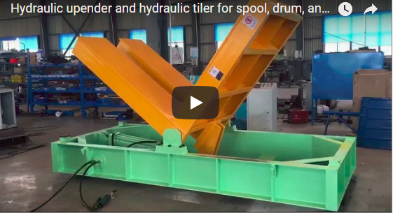
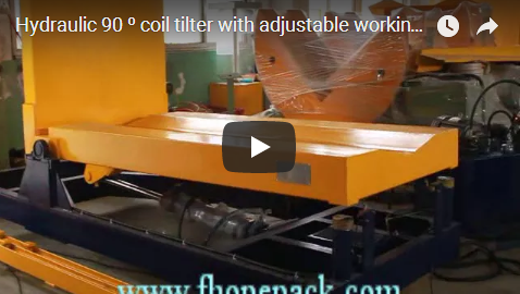
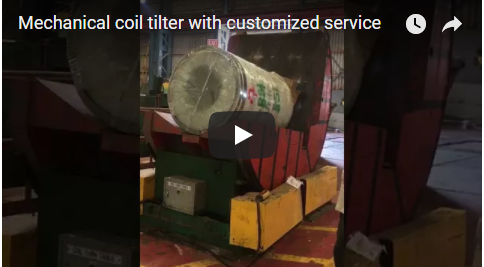
| **Mechanical Coil Upender (FPCT)** | 90° | Strip steel, aluminum strip, wire rod coils (3–20 t) | Heavy-duty gear-motor, worm reducer, four-roller trunnion |
| **Spool and Reel Tilter** | 90° | Cable drums, wire spools, flanged reels | Roller chain drive with cradled spool fixtures |
| **180° Mold / Die Turnover** | 180° | Stamping dies, injection molds, precast structural panels | Dual-cylinder hydraulic drive or geared continuous turnover |

The mechanical upender is the primary solution for metal coil processing. Driven by an electric gear-motor combined with a self-locking worm drive and an electromagnetic fail-safe brake, it holds full rated tonnage firmly at any intermediate angle—even during sudden utility power blackouts. Spool tilters utilize recessed cradles to protect delicate reel flanges, while 180° flippers allow safe die separation and maintenance.

<h2 id="how">How a mechanical upender works</h2>

The 90° mechanical upending cycle operates through four synchronized steps:

1. **Load.** An overhead crane (with C-hook), forklift, or automated coil transfer car sets the coil onto the 90° L-shaped cradle. The contact face features a V-saddle lined with high-density polyurethane (PU) or replaceable hardwood boards to prevent strip marking.
2. **Tilt.** The operator initiates the cycle from the external control console. A frequency-inverter-controlled motor drives helical bevel gears and a precision worm gearbox. A heavy-duty four-roller trunnion system distributes the radial load and structural bending moments across the base frame as the body tilts smoothly.
3. **Stop.** Dual mechanical dead stops and redundant proximity limit switches decelerate and halt rotation precisely at 90°. The combination of gear tooth engagement and an electromagnetic motor brake provides positive mechanical locking at any intermediate position.
4. **Unload.** With the coil stabilized in its new orientation, the forklift tines, crane grab, or automated walk-beam conveyor safely removes the payload for the next processing stage.

Operating controls are consolidated on an exterior control pedestal with two-hand pushbuttons or an optional industrial radio remote, keeping personnel outside the machine's dynamic swing envelope.

<h2 id="specs">FPCT upender data</h2>

Standard engineering specifications for the FPCT mechanical series:

| Model | Rated Payload | Drive Power | Tilt Cycle Time (90°) | Machine Weight (Approx.) |
| :--- | :--- | :--- | :--- | :--- |
| **FPCT-03** | 3 t | 1.3 kW | 50–90 s | 1,800 kg |
| **FPCT-05** | 5 t | 2.0 kW | 50–90 s | 2,600 kg |
| **FPCT-10** | 10 t | 2.5 kW / 4.5 kW | 60–90 s | 4,200 kg |
| **FPCT-20** | 20 t | 7.8 kW | 60–100 s | 7,500 kg |

- **Tilt Speed Regulation:** Variable Frequency Drive (VFD) soft-start and soft-stop acceleration profiles.
- **Electrical Supply:** 3-phase AC 380 V / 480 V, 50/60 Hz (configured to site requirements).
- **Bed Liners:** 15–20 mm high-molecular polyurethane (PU) wear plates.

<h2 id="example">Sizing example: an 8 t coil</h2>

Consider a production facility handling steel coils with a maximum gross weight of 8 t, operating at an average requirement of 25 coils per 8-hour shift.

| Design Verification Step | Engineering Calculation | Selected Outcome |
| :--- | :--- | :--- |
| **Dynamic Service Factor** | 8 t × 1.25 safety reserve | 10.0 t design threshold → **FPCT-10** |
| **Machine Hourly Capacity (Slowest)** | 3,600 s ÷ 90 s | 40 tilts/hour |
| **Machine Hourly Capacity (Fastest)** | 3,600 s ÷ 60 s | 60 tilts/hour |
| **Shift Requirement Verification** | 25 coils ÷ 8 h = 3.12 coils/hour | Pass (3.12 ≪ 40 tilts/hour capability) |

**Conclusion:** The FPCT-10 provides optimal mechanical reserve without running the reducer near thermal or structural limits. While the machine itself can deliver 40 to 60 single-motion tilts per hour, total line throughput is dictated by crane rigging, forklift approach intervals, and strapping cycle times.

<h2 id="selection-checklist">Selection checklist</h2>

Verify these physical and operational specifications before ordering a tilter:

1. **Payload Boundaries:** Maximum gross coil mass (t), outer diameter (OD max/min), inside core diameter (ID), and maximum coil face width.
2. **Kinematic Stroke:** Standard 90° upending or 180° inverted rotation.
3. **Shift Throughput:** Peak batches per hour and total cycles per shift to determine motor thermal class.
4. **Logistics Interface:** Loading method (crane with C-hook, counterbalanced forklift, walking-beam car, or powered chain conveyor).
5. **Cradle Surface Protection:** Plain steel plate, replaceable hardwood, or bolted high-durometer polyurethane protection plates.
6. **Civil Engineering Constraints:** Surface floor mounting (ramp access) vs. flush-floor pit-mounted installation.

<h2 id="safety">Safety: EN 415-10 and ISO 12100</h2>

Heavy industrial upenders fall within **EN 415-10** (Safety of packaging machines and integrated lines) and must meet **ISO 12100:2010** risk assessment guidelines:

- **Perimeter Guarding:** Rigid perimeter wire-mesh fencing prevents worker entry into the cradle travel radius during movement.
- **Access Interlocks:** Interlocked access gates equipped with Category 4 / PLe safety limit switches immediately cut drive power if opened during operation.
- **Fail-Safe Holding:** The combination of worm drive gearing and spring-applied, electrically released disc brakes prevents gravity-induced descent during sudden voltage dropouts.
- **Travel Over-run Protection:** Redundant electro-mechanical limit switches back up primary encoder tracking at terminal 0° and 90° positions.

<h2 id="engineering-faq">Engineering FAQ</h2>

**Q: What happens if electrical power fails mid-turn at 45°?**
A: The self-locking worm gearbox combined with the spring-applied fail-safe disc brake mechanically locks the rotating cradle immediately. The coil remains firmly suspended in place without downward drift.

**Q: What is the true floor-to-floor cycle time?**
A: The 90° rotation takes 50–90 s depending on payload and VFD ramp settings. Total floor-to-floor time (including forklift placement, sensor verification, rotation, and removal) generally averages 2.5–4 minutes per coil.

**Q: Can the FPCT upender handle flanged cable drums or wire spools?**
A: Yes. For flanged spools, the flat bed is configured with a recessed concave cradle or custom locking lugs to prevent the flange rims from rolling laterally during upending.

**Q: Does the equipment require a concrete pit?**
A: No. Standard FPCT upenders are surface-mounted directly to a flat reinforced concrete slab (minimum 200 mm depth, 30 MPa compressive strength) using chemical wedge anchor bolts. Pit mounting is optional when top-of-cradle flush floor loading is preferred.

<h2 id="next-step">Next step</h2>

1. **Submit Coils Parameters:** Send your maximum coil weight, OD/ID dimensions, width, and facility voltage to info@fhopepack.com.
2. **Engineering Selection:** Our application team matches the appropriate machine framework, cradle liners, and integration layouts.
3. **Proposal & Drawing:** Receive a formal layout drawing, mechanical specification sheet, and commercial quotation within 24 hours.

<h2 id="related-reading">Related reading</h2>

- [Mechanical coil upender tilter (product)](https://www.fhopepack.com/Mechanical/Coil-Upender-Tilter.html)
- [Spool and drum tilter (product)](https://www.fhopepack.com/Mechanical/Spool-Drum-Tilter.html)
- [Slit coil upending, transport and eye-through wrapping](https://www.fhopepack.com/videos/a-production-managers-guide-to-slit-coil-upending-transport-and-eye-through-wrapping/)
- [FHOPE wire spool tilter upender](https://www.fhopepack.com/videos/fhope-wire-spool-tilter-upender/)
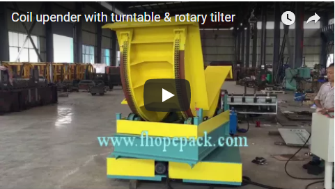
- [Coil upender with turntable](https://www.fhopepack.com/videos/coil-upender-with-turntable-rotary-tilter/)

<h2 id="sources">Sources</h2>

- FHOPE Engineering Technical Documentation: FPCT Mechanical Upender & Tilter Series.
- Video Demonstration: Factory Floor FAT Testing of 10 t Heavy-Duty Coil Tilter with Perimeter Guarding.
- Safety Standards: EN 415-10:2014 (Packaging machines safety); ISO 12100:2010 (Risk assessment and risk reduction).

<p><strong>Last reviewed:</strong> 2026-10-19</p>